I recall the longish current drive discussions earlier in this thread, or was it the last Blowtorch thread ... regardless, it's interesting that there's a whole book on the topic. There doesn't appear to be many copies around (I looked on Worldcat etc.), but then it's a niche topic. I found the author's website:Joe,
One well meant advice.
Try to deepen your skills on LS current drive, for instance with the book in the attachment.
That will help you to better understand Bill’s comment.
Hans
.
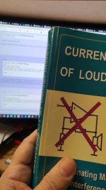
Current-Drive - The Natural Way of Loudspeaker Operation
Joe,
One well meant advice.
Try to deepen your skills on LS current drive, for instance with the book in the attachment.
That will help you to better understand Bill’s comment.
Hans
.
Hans, I will deepen your skill, the book was published in 2010 and I have had the book for 11 years.
You do the maths.
Also, John Curl and myself had a series of discussions back then with Esa, this was at the time Esa was knocked back by AES. I even asked Esa what was the minimum ratio of source impedance to load to qualify current drive? This is a critical question (and you would understand it if you understood the book) for what he considered the minimum ratio of current drive. I had the ratio 5:1 min in mind. Guess what? The ratio Esa came up with was 5:1 min. I also told him that current drive is not going to take off, it would not get beyond DIY and it would be limited to active speakers perhaps. I have been proven right on that - we have active loudspeakers on the market that does use it on mids and tweeters. Nobody has done it on the bass unless they used a LOT of mechanical damping, they haven't figured it out to do it properly on the bass... until now - I am working with a loudspeaker manufacturer to bring out a 3-Way all active speaker system that does. Some will say that is not possible but control the current versus frequency, you can control damping under current drive as well, and even better than voltage drive. Vary the current with frequency and you can effectively dial-in the damping using current drive, something you cannot be done with voltage drive. Mind you, this is only a solution (or fix) for active speaker systems, not passive.
I told Esa that this minimum 5:1 ratio needs to work with voltage sources. He then sent me several schematics about how this can be done and that I would keep it confidential - which I have and they are stored on this computer. The problem is that the 'fix' which is just another word for 'solution' has a big downside: The voltage sensitivity is 15dB below the average and since the average is 87dB, you do the maths and 72dB? Needs amplifiers with huge voltage swings and not high current. I have not seen Esa publish them anywhere (I am sure I would have been alerted) and if he has or not, I have kept his confidentiality. The 'fix' or 'solution' I am working on does not have this problem. It lowers efficiency slightly but not voltage sensitivity. I hope you know the difference.
Anything else?
So when Bill refers to Purifi's solution as a 'fix' and that is OK, then how come that I cannot use the word 'fix' referring to the same Purifi's solution and he claims the context is the same? Has he taken leave of his senses? The context is identical.
He was just being irrational and he made a goose out of himself and he owes me an apology.
Attachment: My well-thumbed copy of Esa's book. The forum in the background - so almost real-time! 🙂
Attachments
Last edited:
I suppose if the speaker is doing this via back EMF, that could explain why cables (with differing connection impedance) might sound different. I wonder under what circumstances this is happening? Ear breaking loud perhaps?
Aware of KEFs efforts to make the speaker impedance, as seen by the amplifier, tend toward resistive across the audio band, with their claim that it makes the amplifier not have to work as hard to drive the speaker.
Is that just another way of saying the same thing?
One would think a speaker with darn close to a resistive drive nature would be less susceptible to "mix 'n match" of cables, amplifiers regarding how it sounds. If everyone designed speakers with this aspect paramount, perhaps the mix and match thrash at that level would eventually die among audiophiles. Wonder what impact that would have on the accessory and amplifier industry?
Put a 0.1 ohm across the speaker terminals, a 1 Ohm in series. Your 95db driver is now 85. Let's see the back EMF of the speaker influence the output of the amp it would take to drive that. Burn a bunch of power in the 1? That's what the heatsinks on the back of the cabinet are for. Of course I jest, but there's probably an effective passive technique somewhere between brute force and nothing. Right now I'm listening to "nothing" between the speaker terminals and amp, besides the wire.
Hi Joe
Much appreciated that you made the effort to read it, alas the animous from others is one-sided and goes back to past history.
Yes, your 0.1 Ohm thought experiment is right on! This would suppress these "impedance modulations" that Puirifi talks about and they are also related to that 15 to 20dB reduction in distortion that shows up in current drive. But alas, current drive and 0.1 Ohm is not a real-world fix (there is that word again), in other words we need to look for other solution a la fixes. What Purifi has done is clearly explained with graphs they have made public: At any particular frequency and excursion the inductance stays the same. The logic is not hard to understand, "impedance modulations" is the current of the amplifier being modulated by changes in inductance while music (or even test signals) and it is measurable.
That KEF is also looking closely at this does not surprise me. There are a number of people who are now doing 'current EQ' or equalisation as part of the fix.
A few years ago some of us was talking about these things and very slowly a momentum is building. It is not about current-drive perse' - but it is being at least partly current-drive able to show the way to use it with normal amplifiers.
Yes, reducing effects in cables has been known about for some time. It is part of the mix.
Here is something most people can try: If you have an 8 Ohm speaker, get your hands on a pair of 8 Ohm resistors, minimum 10 Watt rating. Fit that in parallel with your speaker. You can even just fit them across the output terminals of your solid-state amplifier. See if you can hear a difference? Most likely you will be pleasantly surprised. This is poor man's current equalisation.
If you have an nCore Class D amplifier (a lot better than earlier model UcD), these can drive 2 Ohm easily and try a 3 Ohm 20 Watt min resistor, and the result is even better. I once owned a pair of NC400.
Yes, this is hands-on, this is good. Better than the nay-sayers and doubters who don't want to get their hands dirty?
Maybe I should be optimistic and hope they try it - almost everybody on this thread could try it. Just a couple of 8 Om resistors? That'd be nice.
That you know of.Nobody has done it on the bass unless they used a LOT of mechanical damping, they haven't figured it out to do it properly on the bass... until now
Well, at least Purify is trying to make a change although not everybody understands it.
Hans
You are right, it is not easy. Somebody I considered a teacher said "Thinking voltage is easy, thinking current is hard."
Thinking is voltage is easy, it is intuitive. Thinking current is counter-intuitive. It's like watching a negative and trying to make sense of it. Voltage is like a signal on an oscilloscope, instinctively you know it is voltage vertically and lateral is time. Try put a current signal on an oscilloscope. You can't - unless you convert it to a voltage where the voltage is proportional to the current. This is how we do it.
That you know of.
Hi Allen.
I have done it. Come here and I will show you how it's done. I know others who know how it is done, I told them and they understood how it works. Has anybody out there in the wide world figured it out? Perhaps. But I have seen no evidence of it. But it was only a matter of time before it got figured out. Esa in his book and anything he has said since, he does not seem to think it can be done. Actually, way back in Blowtorch history I gave chapter and verse how it was done. I have since repeated it a number of times. All I got was "Joe is back spouting nonsense again" and the usual negativity. I was judged by these people a long time ago and they are never going to say sorry, ever! Oh well, they have done it to persons greater than me - like John Curl. Sigh.
Now I gotta get some work done - no lockdowns and all the numbers are going in a good direction. 🙂 🙂 🙂
Last edited:
People have been adjusting bass damping on valve amplifiers.
You show me yours and I'll show you mine?
You show me yours and I'll show you mine?
Make the amplifier supply the same current at all frequencies in the LF. Reshape the current through the voice coil and dial in the added damping you want. It's not hard when you know what you got to do. But to be honest, is anybody here even interested?
I can turn a sealed box Butterworth 2nd order into Bessel 2nd order with touching the cabinet, it is all done on the electrical side. Yep, you can increase damping on the electrical side, but not if it is a current source. Think about and you will realise why: A voltage source relinquishes control over the current, a current source gives you back the control. It works because any change in current gives a proportional change in dB-SPL at 1 Metre, and this works at all frequencies, which I proved and posted actual measurements and graphs with numbers and equations on the Blowtorch - THREE TIMES!
Each time, they just got lampooned! After the third time, Scott Wurcer must have gotten some of it because he asked two questions that were the right questions to ask. But I am wiser now, I said those two questions were measurements he was asking for and I sure was NOT going to post them. The reception party would have slashed that too!
So that is where we are up to.
I saw that Purifi was mentioned here, in Blowtorch we were often discouraged talking about speaker (have no idea why?), so it's good to see it OK here. So I chimed in. But to some, their old habits never die!
Yep, I saw Bill talking about Purifi having a 'fix' and I explained what the 'fix' was and he goosed himself that me calling it a 'fix' was somehow arrogance, yet when I was only using his word back. He called it 'weaponised arrogance' and claimed the use in his case was OK because he had used it in a different context. No, he was not and in fact, go back and read it yourself, we were both using the word in exactly the same context and same subject. I have asked that he apologise. But I doubt that he is man enough to do so. What he did was purely out of meanness, and he knows it!
Back to work... 🙂
I found the author's website:
Current-Drive - The Natural Way of Loudspeaker Operation
Thanks! There he shows a passive way (aside from using just a series resistor) that uses a transformer; Clean-current speaker project | Current-Drive - The Natural Way of Loudspeaker Operation
He indicates that a power transformer is used, "Because there are no commonly available audio transformers of the needed size that come anywhere close to the suitable turns ratio (here 1:4.4)"
There are some uncommonly available ones. I have a set of Atlas T11s, a +/- 1.5db, 60 to 20K line matching transformer, which has a 4,8,16 Ohm secondary taps - and a 90 Ohm primary, among others. That's a 22.5:1 impedance ratio available.
In the article, he states "the transform ratio of impedances becomes about 19, and thus the speaker impedance of 8 Ω appears on the primary side as 0.42 Ωhm. Mine would be 0.35 Ohm. Going to the 8 Ohm tap on the secondary, 0.7 - etc.
He then introduces 9 X 0.42 = 3.8 Ohm of resistance into the primary circuit and states that the amplifier will see about 4 Ohms. Fair enough. I could use a 9 - 10X, resistor on the 0.35 or 0.7 Ohm "input" taps.
Where I get lost is, regarding a 9-10X resistor to transformer input impedance: "(naturally the same would follow also by considering the issue on the secondary side), so the attenuation of the driver's harmful EMF currents will be, in principle, already 20 dB"
Is this because the 8 Ohm driver cant drive current looking back into 90 Ohms in the same way it could into, say, 1 Ohm of amplifier / cable output impedance?
He then states the loss of this arrangement is 10db; "With the impedance ratios used, 10% of the power fed by the amplifier ends up to the driver itself, the rest being consumed in the series resistances". Rendering my 85db speakers 75db, or my 25W amp virtually 2 watts and change.
It's certainly easy enough to try as an experiment -
Last edited:
Clean-current speaker project | Current-Drive - The Natural Way of Loudspeaker Operation
Yes, there are significant losses here. A fairly flattish impedance presented to the voltage source amp, this means that "impedance modulations" will be reduced. I still say this is the cause of distortion that will be reduced. Look for ways to do that and you get similar results to current-drive. When looking at it from this angle, there are more ways than one to skin a cat. We can still use conventional amplifiers and find ways to get the lower distortion (10dB or better). I know of three, and this looks like one of them, but perhaps the third best?
It looks very close to the ratio 5:1 that I asked Esa about, back quite some years now. We both agreed on that ratio. Is Esa around these days to comment on this?
Last edited:
I always think of you as the FLAT IMPEDANCE MAN, Joe! 😀
And it must make a feedback amplifiers job easier, with all the impedance phase angles that most crossovers throw at them.
Did you see my investigations of all this?
Flat Impedance and Flat Power response design.
Could be complete rubbish, of course. I did try all that Zobel stuff on drivers. It was hard to tell if it was better.
Jeff Bagby did some calculations for good impedance:
Last edited:
Placing resistors in parallel on a high feedback (= low Zout) amplifier does little or nothing to 'flatten' the impedance seen by the amp or the speaker - it just lowers it.
For current control drive, you would expect the voltage as measured at the speaker terminals to change with frequency because the speaker impedance changes with frequency. This is known as 'compliance' (not to be confused with speaker or cartridge mechanical compliance). I suspect that there may be some improvement when you place a resistor in parallel with the speaker in current drive because you are reducing the compliance requirements (and hence opportunity to clip) at the expense of wasting a lot of power in the parallel resistor.
For current control drive, you would expect the voltage as measured at the speaker terminals to change with frequency because the speaker impedance changes with frequency. This is known as 'compliance' (not to be confused with speaker or cartridge mechanical compliance). I suspect that there may be some improvement when you place a resistor in parallel with the speaker in current drive because you are reducing the compliance requirements (and hence opportunity to clip) at the expense of wasting a lot of power in the parallel resistor.
I think that's why he called it poor man's current eq, something simple to try, not current drive.
Yes of course it does, but to what purpose.Placing resistors in parallel on a high feedback (= low Zout) amplifier does little or nothing to 'flatten' the impedance seen by the amp or the speaker - it just lowers it.
If the sound improves with a 8R par. to a low Zout amp, it can only mean IMO that the amp is not a perfect voltage amp.
Hans
My own experience with current drive shows a more moderate reduction in distortion (likely driver dependent), but the most striking aspect is the sharpening of imaging.
I would assume that pushing an object with voltage while it actually uses current to do the work would be less accurate than pushing it with current.
It's just the coupling mechanisms and resonances that tend to get in the way.
Edit: oh, almost forgot..the impedance vs frequency (as well as bode plot/phase margin of the NFB system) of the conversion device changes based on the velocity and acceleration as well, be it speakers, steppers, brushless 3 phase motors, linear motors. I've started discussion with a large motion control manu to implement this new advance. No need to dull a response down when you don't have to.
It's fun how this stuff crosses engineering boundaries from audio to various other motion control technologies.
ps..been trying to get an intern in for two years from the nearby uni to work this code for a thesis, but the pandemic killed it. sigh
John
Last edited:
I think that's why he called it poor man's current eq, something simple to try, not current drive.
Exactly.
Placing resistors in parallel on a high feedback (= low Zout) amplifier does little or nothing to 'flatten' the impedance seen by the amp or the speaker - it just lowers it.
Au contraire.
Take a look at the two attachments and that 8 Ohm resistor can make quite a large change.
The first one is impedance, Red is before 8 Ohm parrallel and Blue has it.
The second is arguably even more important, is the result to the electrical current phase angle, again Red and Blue.
But what is more, this results in a reduction of distorted current and is measurable.
Attachments
Last edited:
Hi Steve
How is Portsmouth these days. I just recently flew over it in MSFS 2020. 😀
NO THANKS! 🙁
Yes indeed. 😉
How is Portsmouth these days. I just recently flew over it in MSFS 2020. 😀
I always think of you as the FLAT IMPEDANCE MAN, Joe! 😀
NO THANKS! 🙁
Yes indeed. 😉
Interestingly, sometimes loading a voltage regulator with a resistor improves load circuit performance. Could be a similar effect. One possible explanation that has been put forth is that regulator or amplifier output devices may have higher gain at higher current. There may be other possible reasons why system behavior changes from what would be expected using a simple ideal voltage source model.
This implies that you have measured this current distortion to the speaker, so please could you show the measurement.Exactly.
Au contraire.
Take a look at the two attachments and that 8 Ohm resistor can make quite a large change.
The first one is impedance, Red is before 8 Ohm parrallel and Blue has it.
The second is arguably even more important, is the result to the electrical current phase angle, again Red and Blue.
But what is more, this results in a reduction of distorted current and is measurable.
Hans
This implies that you have measured this current distortion to the speaker, so please could you show the measurement.
Hans
I know this is not an unreasonable question, but alas...
For reasons I explained earlier, the answer is sadly no. I know from past experience what will happen. Also, it is not one measurement, but a series of measurements. I am awaiting a 6.5" driver with characteristics that are similar or the same to a driver I already have here, except one parameter is significantly different - this gives me an opportunity to make a certain measurement where I vary an external inductor while keeping an eye on the response and distortion. It is way too intricate to explain here and you saw Bill's meanness to me yesterday - and egos rather than science will rule. So I just keep going ahead and will publish when and where it suits me and it won't be here, that's for sure. But I do understand your interests and in a few months keep in touch with me.
Cheers, Joe
PS: You are on the right track when you said: "implies... current distortion to the speaker."
- Home
- Member Areas
- The Lounge
- The Black Hole......