Also possible to use a two Lundhal Trasformer, with ratio 1:4 as LL1674 or ratio 1:2 as LL1676, connected directly to flip-flop, simple solution.
Hi Ray
this is great, to have a custom product, could you posting the link for Aikido Mfb? So, do you want to try both solution? but with Aikido Mfb you have to use only single ended or is possible to go with balanced? In the kit on Broskie's site there isn't this product with differencial input
Emilio
I plan to try both the BCF and the Aikido in different projects.
The Aikido MFB has a single-ended input. I should also have added that the configuration Broskie supplied me with uses the DC offset from the LP filter (about 1.6V) to bias one half of each 12AX7, so no cap required at the input of the Aikido. The Aikido MFB isn't listed on Broskie's Glassware site so you would have to contact him to obtain one - be warned he's well known for not being a good responder to mails.
Ray
Also possible to use a two Lundhal Trasformer, with ratio 1:4 as LL1674 or ratio 1:2 as LL1676, connected directly to flip-flop, simple solution.
or a TVC like the Silk...
I plan to try both the BCF and the Aikido in different projects.
The Aikido MFB has a single-ended input. I should also have added that the configuration Broskie supplied me with uses the DC offset from the LP filter (about 1.6V) to bias one half of each 12AX7, so no cap required at the input of the Aikido. The Aikido MFB isn't listed on Broskie's Glassware site so you would have to contact him to obtain one - be warned he's well known for not being a good responder to mails.
Ray
I knowed, I have sent an email the last week and I don't received answers. I don't have hurry, I'll wait your testing about both products, then I see the way to get them. Maybe to ask you if the possible to buy it for me, after your test, of course.
I've been off-line for a few weeks and just came back to a storm of activity on this thread! Ray - looks like your PCB is getting very popular. I reckon you should increase the price to recompense you for all the time its taking you not just to design it, but to organise the group buy.
Anyway, I have finally put my prototype no-DAC, which has been living on a shelf and working just fine, into a proper box. Now my system is all balanced, and its also bi-amped. I use a Broskie balanced potentiometer for volume control - I use the mono boards, one atop each amplifier, right behind the speaker. So my 'pre-amp' is simply a source selector. Input/ output connectors are 3.5mm phono (TRS) sockets. One stereo socket per channel.
So I have now built up a new box for my 'pre-amp' and mounted the no-dac inside the same case, wired directly to the source selector.
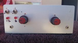
Here is the front view. The 2 switches at top left hand corner manage the power to the JLSounds board. One supply for the 'dirty' USB side of the board, a separate supply for the 'clean' isolated side.
Anyway, I have finally put my prototype no-DAC, which has been living on a shelf and working just fine, into a proper box. Now my system is all balanced, and its also bi-amped. I use a Broskie balanced potentiometer for volume control - I use the mono boards, one atop each amplifier, right behind the speaker. So my 'pre-amp' is simply a source selector. Input/ output connectors are 3.5mm phono (TRS) sockets. One stereo socket per channel.
So I have now built up a new box for my 'pre-amp' and mounted the no-dac inside the same case, wired directly to the source selector.
Here is the front view. The 2 switches at top left hand corner manage the power to the JLSounds board. One supply for the 'dirty' USB side of the board, a separate supply for the 'clean' isolated side.
Attachments
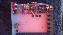
Here is a look inside. The JLSounds board is on the right. To the left of JLSounds is a small vero board with the flip flop. Then to the left of this are the transformers. You can see the 2 power switches on the front panel (LHS of the picture) and the 2 selector switches. I have only wired the no-dac into the selector switches for the moment, I want to make sure that its working before I wire up the other inputs.
You can also see a few voltage regs. The dirty power supply is a 12V SMPS. This goes through a 7809 then a 7805 before the power goes to the board. The 'clean' supply is a 6V SLA battery as described in my earlier posts. The 6V goes directly to the flip flop, and also through another 7805 before it goes to islolated side of the JLSounds board.
You can also see a few voltage regs. The dirty power supply is a 12V SMPS. This goes through a 7809 then a 7805 before the power goes to the board. The 'clean' supply is a 6V SLA battery as described in my earlier posts. The 6V goes directly to the flip flop, and also through another 7805 before it goes to islolated side of the JLSounds board.
Attachments
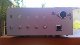
Not much to see on the back. There is an input socket for the power (DIN socket) top right hand corner. You can see the USB input for the JLSounds below that. To the left are the other inputs. I have mounted sockets on the bottom row (left) and I still need to put sockets in the top row (right).
Attachments
This morning I've been listening to music through both the single-ended and flip-flop boards (not at the same time I hasten to add!). I've been using my home cinema amp and speakers as a test platform so no really critical listening so far.
I installed the SE board into my original project, replacing my initial simple filter and mute board. Although essentially the same circuit I did make some changes; I replaced the 22uF DC blocking caps with some 1uF caps that are mounted off-board, the -3dB filter point is at 80KHz instead of 40KHz. It sounds nice. Here's a picture of the board in situ;

I then moved on to testing the flip-flop project. If you've been paying attention you'll know this is a balanced set up with a Broskie BCF buffer stage. Anyway, it worked first time and sounds excellent, noticeably better than my initial project (I'm not saying that the flip-flop is better than the SE as they are significantly different projects and much more time and money has gone into the flip-flop project). -3db filter point for this project is 80KHz. Here's a picture of the flip-flop project;

Tomorrow I'll do some more critical listening in the main system and put the muting through its paces - so far there have been no extraneous noises with either project.
I'll post more information about the projects later.
On the basis of this mornings session it looks as though we have a green light for the group buy for the PCBs.
Ray
I installed the SE board into my original project, replacing my initial simple filter and mute board. Although essentially the same circuit I did make some changes; I replaced the 22uF DC blocking caps with some 1uF caps that are mounted off-board, the -3dB filter point is at 80KHz instead of 40KHz. It sounds nice. Here's a picture of the board in situ;
I then moved on to testing the flip-flop project. If you've been paying attention you'll know this is a balanced set up with a Broskie BCF buffer stage. Anyway, it worked first time and sounds excellent, noticeably better than my initial project (I'm not saying that the flip-flop is better than the SE as they are significantly different projects and much more time and money has gone into the flip-flop project). -3db filter point for this project is 80KHz. Here's a picture of the flip-flop project;
Tomorrow I'll do some more critical listening in the main system and put the muting through its paces - so far there have been no extraneous noises with either project.
I'll post more information about the projects later.
On the basis of this mornings session it looks as though we have a green light for the group buy for the PCBs.
Ray
Last edited:
An externally hosted image should be here but it was not working when we last tested it.
Parafeed output, what do you think?
Here is a look inside. The JLSounds board is on the right. To the left of JLSounds is a small vero board with the flip flop. Then to the left of this are the transformers. You can see the 2 power switches on the front panel (LHS of the picture) and the 2 selector switches. I have only wired the no-dac into the selector switches for the moment, I want to make sure that its working before I wire up the other inputs.
You can also see a few voltage regs. The dirty power supply is a 12V SMPS. This goes through a 7809 then a 7805 before the power goes to the board. The 'clean' supply is a 6V SLA battery as described in my earlier posts. The 6V goes directly to the flip flop, and also through another 7805 before it goes to islolated side of the JLSounds board.
why do you don't had used for power supply something of better? You could to use Lt3080 low dropout, also if I don't see all thing around the regolator, filter and others...What trasformer ratio did you have used?
I reckon you should increase the price to recompense you for all the time its taking you not just to design it, but to organise the group buy.
Thanks for the positive comments and sharing your project with us Hazard.
Your comment above is quite timely as I've been thinking about the effort that will be required to get this group buy progressed; I never expected anything like this level of interest when I offered the spare PCBs. I certainly don't want to appear as though I'm treating this as a money making exercise but equally I don't want to be 'out of pocket'. How would people feel if I was to revise the price to £3 and £4.50 per SE and flip-flop boards respectively - shipping would still be at cost?
Ray
pcb price rise
That is an extremely modest increase Ray and I am happy to pay the new prices.
Barry
That is an extremely modest increase Ray and I am happy to pay the new prices.
Barry
That is an extremely modest increase Ray and I am happy to pay the new prices.
Barry
Agreed.
- Home
- Source & Line
- Digital Line Level
- The Best DAC is no DAC