Do you or does anyone know anything about the algorithm of AMSDM7-512? How does it differ from a plain old sigma-delta?
Do you or does anyone know anything about the algorithm of AMSDM7-512? How does it differ from a plain old sigma-delta?
From the manual:
DSD5 Rate adaptive fifth order one-bit delta-sigma modulator.
DSD5v2 Revised fifth order one-bit delta-sigma modulator.
DSD7 Seventh order one-bit delta-sigma modulator.
DSD5v2
256+fs
Revised fifth order one-bit delta-sigma modulator optimized for rates >=
10.24 MHz.
DSD7
256+fs
Seventh order one-bit delta-sigma modulator optimized for rates >=
10.24 MHz.
ASDM5 Adaptive fifth order one-bit delta-sigma modulator.
ASDM7 Adaptive seventh order one-bit delta-sigma modulator.
AMSDM7
512+fs
Special adaptive seventh order “pseudo-multi-bit” modulator optimized
for rates above >= 20.48 MHz.
Copyright © 2008-2017 Jussi Laako / Signalyst. All rights reserved.
On Audiophilestyle.com Jussi said:
"DSD* modulators are fixed configuration ones while ASDM* modulators are adaptive in various ways based on source signal. So the DSD* ones are simpler and the ASDM* ones are more advanced algorithms. But you can just listen and decide which way you prefer, there is no clear way to say how something sounds and what should be used, apart from the modulator order as discussed above.
Now in the latest beta there's a new special beast called AMSDM7 tailored for >= DSD512 speeds (it is also allowed for DSD256, but then your mileage may vary depending on DAC - i need to do more measurements to see how it behaves in such cases)".
So not really an answer, but then again he's right to keep his cards close to his chest because it's his life's work.
I'm not convinced (but it could be) that it's RTZ or a light variant. Months ago I expected, after measuring and comparing algorithms that the dac output signal would be less than normal, but it wasn't. Being a hardware guy it didn't catch me at the time that Jussi could've adjusted the level in software of course, to match RTZ to NRTZ. I haven't yet implemented RTZ in hardware to compare the software with. Will update here when that's the case.
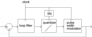
Pseudo multi-bit could mean that he has embedded a pulse width modulator inside a sigma-delta loop, so he can use a quantizer with more levels that can be properly dithered. That works quite well against quantization artefacts, but it requires a high bitrate because the oversampling ratio is less than that of a single-bit sigma-delta with the same bitrate - which would explain why he only recommends it for DSD512.
Attachments

Pseudo multi-bit could mean that he has embedded a pulse width modulator inside a sigma-delta loop, so he can use a quantizer with more levels that can be properly dithered. That works quite well against quantization artefacts, but it requires a high bitrate because the oversampling ratio is less than that of a single-bit sigma-delta with the same bitrate - which would explain why he only recommends it for DSD512.
Nice insight. That's what I would call a RTZ light version. 😀
Funny thing is that I couldn't measure any difference (dynamic range or thd) between this one and the other dsd512 or 256 rates and algorithms, but did when comparing to 128 or 64 rates (slightly higher dynamic range).
So it looks like dsd256 or dsd512 resolution is still there, without the ISI artifacts of the other algorithms available of HQP, at -60dB. So he's done a really good job, at least for the combination of hardware that was used (1 bit CML-logic dac chip). It also works well with 32 tap 1-bit fir dacs, but don't suspect it helps any normal dac chip though.
P.S. that thumbnail there looks a lot like the description of a Axiom/Teledyne Dalsa FIR dac🙂
Last edited:
Nice find! What's your take one jitter specs by having an fpga generate the clock by means of an internal dpll? I agree firdacs or other multibit is the way to go in that case.
DSM topology is more sensitive to jitter than PCM because its actual output frequency is high(more than megahertz). 1 bit DSM in the digital domain has perfect performance, but on the condition that you have the same pulse width between low and high. Clock jitter and the difference between tpdlh and tpdhl are factors to break the condition in the analog domain. They have the same meaning. The recovered clock of PLL is actually 10ps jitter. So is FPGA PLL. The difference between tpdlh and tpdhl is around100ps if you don't have compensation logic(ADN4664 is 120ps. MC10EL35 is 75ps). I'm sure this difference is usually larger than clock jitter. That's why you need to cancel the difference in the beginning to make the best of your clock.
DSM algorithm
IMHO, algorithm competition on DSM is already over. I would say old DSM like SACD isn't sophisticated because it outputs a specific idle pattern(11010010) when in zero input. But now you can find the optimum algorithm even in 5th order which can outperform SACD(probably 7th order). This is the best HP that explains details and leads you to the excellent DSM in the digital domain.
PlayPcmWin / Wiki / PCMtoSDM
I mean the game is over in the digital domain. The playground is only in the analog domain, where no game over exists.
BTW, I modified my DSM designed by the HP above to measure SNR of 1bit DSM. My current one is 5bit DSM, which has 118dB SNR in 256DSD while it has 119dB in 16bit PCM, which can be regarded as residual noise because DSM outputs some pulse even in zero input but PCM do nothing. The degradation caused by DSM is minimal because of the excellent DSM algorithm. You can easily modify bit-depth as long as it is smaller than 5bit. SNR is about 112dB in 2bit DSM(256DSD). 1bit has some unknown trouble. It has a terribly bad number (88dB ?). I guess it has at least 106dB when I fix the problem. My DSM is implemented by four 14bit multi-bit DAC(AD9717). 1bit, of course, doesn't need relative accuracy adjustment since it has only one amplitude. Practically speaking, 2bit can also be adjustment free for music playback. 5bit DSM is better for measurement purpose. If 2bit is adjustment free, I'm sure 2bit DSM is a better solution than 1bit though I need further investigation. Adjustment free means you can use inexpensive low bit-depth(8bit) DAC.
DSM topology is more sensitive to jitter than PCM because its actual output frequency is high(more than megahertz). 1 bit DSM in the digital domain has perfect performance, but on the condition that you have the same pulse width between low and high. Clock jitter and the difference between tpdlh and tpdhl are factors to break the condition in the analog domain. They have the same meaning. The recovered clock of PLL is actually 10ps jitter. So is FPGA PLL. The difference between tpdlh and tpdhl is around100ps if you don't have compensation logic(ADN4664 is 120ps. MC10EL35 is 75ps). I'm sure this difference is usually larger than clock jitter. That's why you need to cancel the difference in the beginning to make the best of your clock.
I'm not sure I follow your reasoning. Are you using a interleaved dac structure which makes it so sensitive to changes in propagation delay, or is it something else that does this?
Normally speaking the difference in propagation delays of logic don't equate to the jitter specs of it at all, in that case cmos would be horrible but they're obviously not.
For clocks, normally the difference in timing from the positive edge to the next defines jitter, as those edges dictate jitter, afaik the negative edge doesn't influence the jitter(apart from clock feedthrough).
Do you clock on both (up and down) edges?
Thanks! Just placed an order for some 7474 Flip-Flops
Make sure you use ground plane and bypass them properly, they are very fast.
I've used them with success.
T
IMHO, algorithm competition on DSM is already over. I would say old DSM like SACD isn't sophisticated because it outputs a specific idle pattern(11010010) when in zero input. But now you can find the optimum algorithm even in 5th order which can outperform SACD(probably 7th order). This is the best HP that explains details and leads you to the excellent DSM in the digital domain.
PlayPcmWin / Wiki / PCMtoSDM
I mean the game is over in the digital domain. The playground is only in the analog domain, where no game over exists.[/QUOTE
Personally I'm more inclined to say that software is still lagging the hardware capabilities we should use, as in: where to find 5 or 7 channel dsd256 or dsd512 output capabilities or how to tell the pc to not have e.g. 2 channel dsd256 1 bit but instead have it spit out 8 bit dsd64 (together with matching algorithms of your choice to tailor specific dacs or analog filtering)?
There's still a big void in the software department for developing algorithms for this, partly because there's no driver written to accomodate these output formats. The hardware is easy to design if these options would be there and analog filtering would be easier to implement, but I admit all this is a bit like the chicken or the egg kind of thing.
Main objective is imho to have less destructive format conversions on the pc (from dsd to pcm and vice versa, or think studio work flow: editing, echo, mixing etc) and to put less strain on the analog parts.
BTW, I modified my DSM designed by the HP above to measure SNR of 1bit DSM. My current one is 5bit DSM, which has 118dB SNR in 256DSD while it has 119dB in 16bit PCM, which can be regarded as residual noise because DSM outputs some pulse even in zero input but PCM do nothing. The degradation caused by DSM is minimal because of the excellent DSM algorithm. You can easily modify bit-depth as long as it is smaller than 5bit. SNR is about 112dB in 2bit DSM(256DSD). 1bit has some unknown trouble. It has a terribly bad number (88dB ?). I guess it has at least 106dB when I fix the problem. My DSM is implemented by four 14bit multi-bit DAC(AD9717). 1bit, of course, doesn't need relative accuracy adjustment since it has only one amplitude. Practically speaking, 2bit can also be adjustment free for music playback. 5bit DSM is better for measurement purpose. If 2bit is adjustment free, I'm sure 2bit DSM is a better solution than 1bit though I need further investigation. Adjustment free means you can use inexpensive low bit-depth(8bit) DAC.
That's some hard core developing you do there, hats off doing fpga, programming, dacs and analog design, thats not an easy task!
1 bit should be perfectly able to reach the levels you stated (way above 100dB SNR anyway), but I have no experience using 1 bit dsd with an off the shelf dac. All kinds of things going on in those chips.
And looking at that chip, it's got an interleaved structure so no wonder you need those clocks adjustable like you said. Curious to see more of this.
I'm not sure I follow your reasoning. Are you using a interleaved dac structure which makes it so sensitive to changes in propagation delay, or is it something else that does this?
Normally speaking the difference in propagation delays of logic don't equate to the jitter specs of it at all, in that case cmos would be horrible but they're obviously not.
For clocks, normally the difference in timing from the positive edge to the next defines jitter, as those edges dictate jitter, afaik the negative edge doesn't influence the jitter(apart from clock feedthrough).
Do you clock on both (up and down) edges?
If your clock is 10megahertz with no jitter, you can output 5 megahertz waveform. But your 5megahertz isn't exact 50% duty in the real world. If your logic has 2ns tpdlh and 3ns tpdhl, the period of high is 100+(3-2)=101ns while those of low is 100+(2-3)=99ns. 5 megahertz is entirely guaranteed, but duty isn't. The only condition is the same tpdlh and tpdhl. Clock jitter is a dynamic one which modulates the duty cycle while the difference between tpdlh and tpdhl is static. But for DSM accuracy, both are the same meaning. DSM requires exact 50%duty. I had a considerable improvement when I compensated the difference. After the adjustment, rise and fall time may be the dominating factor.
If your clock is 10megahertz with no jitter, you can output 5 megahertz waveform. But your 5megahertz isn't exact 50% duty in the real world. If your logic has 2ns tpdlh and 3ns tpdhl, the period of high is 100+(3-2)=101ns while those of low is 100+(2-3)=99ns. 5 megahertz is entirely guaranteed, but duty isn't. The only condition is the same tpdlh and tpdhl. Clock jitter is a dynamic one which modulates the duty cycle while the difference between tpdlh and tpdhl is static. But for DSM accuracy, both are the same meaning. DSM requires exact 50%duty. I had a considerable improvement when I compensated the difference. After the adjustment, rise and fall time may be the dominating factor.
I'm assuming this is verified when using both Q as well as the I outputs of the AD971X dac chip? In that case, afaik, you're using the interleaving mode of it which explains it. Otherwise I can't explain it.
Nice insight. That's what I would call a RTZ light version. 😀
Funny thing is that I couldn't measure any difference (dynamic range or thd) between this one and the other dsd512 or 256 rates and algorithms, but did when comparing to 128 or 64 rates (slightly higher dynamic range).
So it looks like dsd256 or dsd512 resolution is still there, without the ISI artifacts of the other algorithms available of HQP, at -60dB. So he's done a really good job, at least for the combination of hardware that was used (1 bit CML-logic dac chip). It also works well with 32 tap 1-bit fir dacs, but don't suspect it helps any normal dac chip though.
If you should want to figure out the difference between the algorithms, maybe you could capture the bitstream with a digital oscilloscope or a logic analyser and see if the bit patterns tell you anything?
P.S. that thumbnail there looks a lot like the description of a Axiom/Teledyne Dalsa FIR dac🙂
It's a picture from an article about a hobby DAC I designed and made, see The valve DAC - Submicron silicon meets submillimetre vacuum. I implemented three different sigma-delta modulators on an FPGA board, two of them are according to the picture - although I don't use normal PWM but randomly rotated PWM. The third one is a chaotic single-bit sigma-delta.
The concept (but with normal PWM) comes straight from the description of prior art in an old patent by Peter Craven. The patent has passed its due by date and this was prior art, so embedding PWM in sigma-delta loops must have been done for decades.
That's the most wicked and bold design I've ever seen someone do: dac's made with tube oscillators and choice of algorithms etc etc! Must have taken some hours to get that beauty up and running well, do you still use it as a source today, what are its strong points, soundwise?
And:
My bad: I should've said that the AMSDM7-512 algorithm makes the artefacts virtually impossible to hear (ear to speaker, max volume of amplifier, hqplayer software volume controlled to critical volumes with test signal on play), but despite being about 20 dB lower in value as well as being less critical in nature, THD is still higher than I'm supposed to have when actual RTZ encoding would have been implemented. That is, if the scientific papers are true about the effect of this encoding, which I believe they are.
The difference between the other algorithms is pretty big though: with the other algorithms lots of squishy sounds when the appropriate music is played, more muddy, or should I say sloppy sound. E.g. echo's don't fade in a sort of 8 bits hazy or grainy sound, so stage is bigger and more natural.
THD is still highest in that -40 to -60 dB range, of course not taking any signal above -6dB into consideration. The worst is not the distortion per se, but the nature of them: many high order products, which really stand out, as its uncharacteristic for all other levels of playback level (anything else really, from minimum, some of them drowned in noise of course, to the maximum/-6dBFS).
Btw, you get the exact same effect using the volume control by generating the test signal at those levels, so it's not the volume control effect of HQP, it's excellent.
Of course, being prototypes, there could be some layout or other issue that's causing these anomalies, but after many hours of swapping brand, type and frequency of oscillators, psu's, loading and filtering by and of the various flip flops etc etc, I'm at the point of having to make a hardware implementation of RTZ encoding to be sure and compare it against.
Also, using faster logic (about 10 times) does lower the THD levels as well and these really good parts haven't been used yet.
If all this doesn't pay off I'm going to get myself a beer and follow your advice pronto.
Haven't used one before so that'll take some hours getting it set up.
I'm wondering if 16k of memory per logic channel will get me there, any experience at those speeds and needed memory to capture the raw datastream will be much appreciated!
Oke, enough of this ISI talk.
Anyone got any other tech talk or new revelations regarding these no-dac dac's? I'd love to hear some talk about better oscillators, regulators or resistors here🙂
That's the most wicked and bold design I've ever seen someone do: dac's made with tube oscillators and choice of algorithms etc etc! Must have taken some hours to get that beauty up and running well, do you still use it as a source today, what are its strong points, soundwise?
Thank you for the compliment! It took me a large part of my spare time for about three and a half years, but then again, I wasn't in any hurry. Basically I used it to learn more about modern digital design techniques and about switching circuits with valves, among other things. I knew about sigma-delta modulator design methods, but I didn't know Verilog, had never used an FPGA board before and my knowledge of FIR filter synthesis was quite limited (I only knew inverse-DFT techniques, Parks-McClellan didn't ring a bell).
I use the DAC quite frequently and regarding the sound, I certainly like it - see https://www.diyaudio.com/forums/digital-line-level/166807-dac-gallery-24.html#post5067748 for a more detailed comment. Late last year I took it to a luisterdag of a Dutch audio forum ( 24-11-2018 : Alphen -> AfterBabbel - Pagina 8 - forum.zelfbouwaudio.nl ) and the people there seemed to like it as well - even people who normally only listen to non-oversampling multibit converters because they neither like digital filters nor sigma-delta modulators.
If all this doesn't pay off I'm going to get myself a beer and follow your advice pronto. Haven't used one before so that'll take some hours getting it set up.
I'm wondering if 16k of memory per logic channel will get me there, any experience at those speeds and needed memory to capture the raw datastream will be much appreciated!
If have no experience with it either, but if there is a difference in bit pattern due to an embedded pulse width modulator or something like that, I guess you should be able to see that by looking at a few hundreds of bits.
Last edited:
Hi
I have made some tests of a No Dac , consisting of an Amanero with direct DSD software, output to a 74lv1gc79 FlipFlop with only q out .
(If I use a F-F with Q and invQ it produces much higer third harmonic distortion.) This is connected to a RC filter (270 Ohm - 10 nF) and from the filter to a 10K:10K transformer.
The software is Jriver set to convert anything to 2x dsd in DoP format.
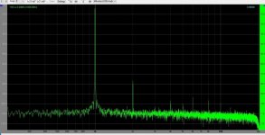
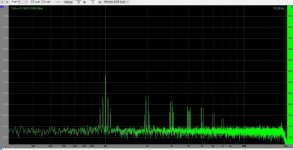
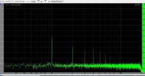
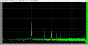
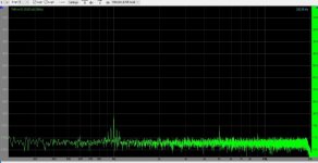
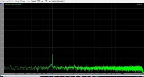
The results are shown in the pics.
1: 0dB
2: - 60 dB WAV from a testdisc downloaded from the web
3: - 60 dB WAV from RME
4: - 60 dB Wav from Wavetones.com
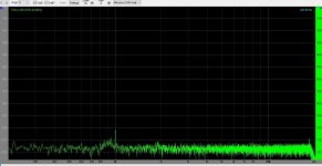
5: - 90 dB WAV fro testdisc
6: - 90,32 WAV fro Hans Polac
7: -100 dB WAV from RME
Surprisingly good result @ 0dB and this continues to about -30 dB.
Suprisingly big difference between the different - 60dB test .wav files.
I will try to get member Hans Polak to make some -50 -60 -70 dB files , as his -90 dB is much cleaner than the test disc.
The -100 dB just to show it can easily resolve that.
I have made some tests of a No Dac , consisting of an Amanero with direct DSD software, output to a 74lv1gc79 FlipFlop with only q out .
(If I use a F-F with Q and invQ it produces much higer third harmonic distortion.) This is connected to a RC filter (270 Ohm - 10 nF) and from the filter to a 10K:10K transformer.
The software is Jriver set to convert anything to 2x dsd in DoP format.
The results are shown in the pics.
1: 0dB
2: - 60 dB WAV from a testdisc downloaded from the web
3: - 60 dB WAV from RME
4: - 60 dB Wav from Wavetones.com
5: - 90 dB WAV fro testdisc
6: - 90,32 WAV fro Hans Polac
7: -100 dB WAV from RME
Surprisingly good result @ 0dB and this continues to about -30 dB.
Suprisingly big difference between the different - 60dB test .wav files.
I will try to get member Hans Polak to make some -50 -60 -70 dB files , as his -90 dB is much cleaner than the test disc.
The -100 dB just to show it can easily resolve that.
Attachments
Bye the way, I have tried to place a LCLC filter in front of the Trafo ( like this: https://www.diyaudio.com/forums/att...racteristic-impedance-4th-low-pass-filter-png) and it makes no difference in the measured performance.
Yes I know that the ultrasonic noise would be lower, but it apparently has no influence in audio band. It could affect amplifying stages after, but even the the soundcards inputamplifier seems not to be affected.Did you also measure the ultrasonic noise? It should make a difference for that.
Hi
I have made some tests of a No Dac , consisting of an Amanero with direct DSD software, output to a 74lv1gc79 FlipFlop with only q out .
(If I use a F-F with Q and invQ it produces much higer third harmonic distortion.) This is connected to a RC filter (270 Ohm - 10 nF) and from the filter to a 10K:10K transformer.
The software is Jriver set to convert anything to 2x dsd in DoP format.
The results are shown in the pics.
1: 0dB
2: - 60 dB WAV from a testdisc downloaded from the web
3: - 60 dB WAV from RME
4: - 60 dB Wav from Wavetones.com
5: - 90 dB WAV fro testdisc
6: - 90,32 WAV fro Hans Polac
7: -100 dB WAV from RME
Surprisingly good result @ 0dB and this continues to about -30 dB.
Suprisingly big difference between the different - 60dB test .wav files.
I will try to get member Hans Polak to make some -50 -60 -70 dB files , as his -90 dB is much cleaner than the test disc.
The -100 dB just to show it can easily resolve that.
Great to also see some -60dB measurements, it's exactly where the problems are.
Strange to see what looks like intermodulation products on some, are you sure there wasn't some 40 Hz or other signal interfering with your measurements?
As an insurance against software upsample errors I always try a few test signals with different resolution and choose the best one, mainly looking at the noise floor. E.g. 1000Hz 16, 20, 24 and 32 bits. My default is 24 bits since most hardware supports it, but test cd's are 16 bits so better not use those. It might be interesting for comparison to e.g. a pcm dac, but when in prototyping that's not of interest yet.
Another important one is using a direct connection to the hardware by using ASIO drivers, but I assume that that's what you get automatically when dsd is the output signal.
With pcm out and using e.g. fpga's or other dedicated hardware outside the pc for converting to dsd this might sometimes get overlooked.
Btw, do you use DoP for a specific reason? It's another software layer that's best left out if possible imho.
270 ohms on cmos is on the edge and depending on exact family, layout or implementation might generate more problems than it solves. Ground bounce or reflections might make some measurement results weird to interpret or behave one day this way, another day different. It might be better to use 500 or 1 K, as most transformers still work fine and filtering is easier. I've heard many flip flops produce better sound but e.g. generate more of that 3rd order distortion you mentioned when pushed too hard.
Dinner is served, gotta go;-)
I am quite sure it is the test files that are different, as I have measured that difference many times and it is the same each time.Great to also see some -60dB measurements, it's exactly where the problems are.
Strange to see what looks like intermodulation products on some, are you sure there wasn't some 40 Hz or other signal interfering with your measurements?
As an insurance against software upsample errors I always try a few test signals with different resolution and choose the best one, mainly looking at the noise floor. E.g. 1000Hz 16, 20, 24 and 32 bits. My default is 24 bits since most hardware supports it, but test cd's are 16 bits so better not use those. It might be interesting for comparison to e.g. a pcm dac, but when in prototyping that's not of interest yet.
Another important one is using a direct connection to the hardware by using ASIO drivers, but I assume that that's what you get automatically when dsd is the output signal.
With pcm out and using e.g. fpga's or other dedicated hardware outside the pc for converting to dsd this might sometimes get overlooked.
Btw, do you use DoP for a specific reason? It's another software layer that's best left out if possible imho.
270 ohms on cmos is on the edge and depending on exact family, layout or implementation might generate more problems than it solves. Ground bounce or reflections might make some measurement results weird to interpret or behave one day this way, another day different. It might be better to use 500 or 1 K, as most transformers still work fine and filtering is easier. I've heard many flip flops produce better sound but e.g. generate more of that 3rd order distortion you mentioned when pushed too hard.
Dinner is served, gotta go;-)
I think I have to use 16 bit files as well as the majority of music CD are in fact 16 bit.
I have measured the same files in a PCM dac. Here the strange intermodulation artifacts are not present in the -60 dB file, but still Hans Polaks files are better:
Building the ultimate NOS DAC using TDA1541A
The makers of Amanero suggest it is best to use DoP in Jriver, and if I don't I cannot get gapless stream out. I haven't tried all possible solutions though.
I think I tried with higher series resistance, and no changes in measurments, but I am not sure.
If I leave the FF out I get much higher 2. harmonic distortion (and also 3. ) ie. take the output directly from the Amanero. I guess the better result with the FF is because the data is clocked out with the bitstream clock.
but what I was referring to was if I use a FF (74hct74) with Q and invQ in balanced mode , the third harmonic becomes higher, without lowering the second.
Actually I find the result very promising, as the -60 db, witch is the worst, the highest harmonic (2.) is -80db down and in some of the files they are harmonic related to the fundamental. Wonder if is audible?
Thanks for the comments and suggestions..
- Home
- Source & Line
- Digital Line Level
- The Best DAC is no DAC