Very interesting, Ray. Since you first started talking about Linux I have been reading up on it. I found this interesting distroI'm beginning to think that the best way to go about this might not involve BBB/botic or the like and perhaps a USB solution is better.
I've been reading various sources on this simple DSD 'DAC' topic and one of the consistent themes is that the 'faster' the DSD the better (for lower noise), ideally aiming for DSD256 or DSD512. I believe BBB will run out of steam beyond DSD128.
Perhaps this is the way to go - a dedicated Linux distribution with HQPlayer or JRiver embedded but apparently controllable from a UPnP control point. There's some interesting info here, though I don't think the guy will win any awards for website design!
AudioLinux - The audiophile realtime plug & play operative system
That maps to an chain something like;
NAS (UPnP media Server) >> AudioLinux/HQPlayer (Upsample to DSD256/512) >> USB >> Reclocker >> DSD 'DAC'
V
V
Other UPnP Renderers
There are a number of interesting and relevant threads over on Computer Audiophile
Ray
AudioPhile Linux | Quality audio on Linux
Looks similar to audiolinux - but its free to download. So definitely worth installing this and checking it out. I'm kust trying to figure out how to install on my PC - I want to keep my Windows OS intact so I am now also trying to learn about dual boot. Ugggh. I just wanna play music.
So at the moment I am still playing with Windows/ Foobar. Based on some advice upthread, I have bought a 74HC flip flop with balanced outputs. I'm wiring it up tonight and will see how it goes.
...I want to keep my Windows OS intact so I am now also trying to learn about dual boot. Ugggh. I just wanna play music.
Looks like you're on your own;
Install instructions v3.0 | AudioPhile Linux
Looking forward to hearing how your next prototype with the flip-flop goes. Good luck.
Ray
About the Layout of the I2S outputs of Nano computers VS output on USB to I2S specialised pcbs : http://www.diyaudio.com/forums/pc-based/269962-nano-computer-i2s-proof-384-khz.html#post4257402
Well I have had some good results today. I bought a 74HC74 flip flop. It cost me $1.98 😉. I have connected the output of the DIYINHK USBtoI2S board to the flip flop, and the complementary outputs of flip flop are connected directly to my Lundahl 1527XL transformers. I have a filter on the secondary of the tranny (15nF in series with 1k). And that's it. Sound is going straight to my balanced amps. Thanks to peufeu for the advice about the flip flop.
And .... its sounding good. The flip flop has adressed the problems I had when the USB board was trying to drive the transformer directly. ie the bass is now at the correct level, and the overall output level is much higher (I had to turn amps up to 11 before, to get a normal listening volume).
I am listening to some recordings my audio buddy made through my Tascam DSD recorder. We have been recording LPs at DSD128, and playing these back right now -- wow, sounding very good.
The whole thing is only prototype and far from optimised. The power is from a computer SMPS, 5 volt output is going directly to flip flop and I am using a 3.3V reg between the 5V and the USB board. And the wiring - well I grew up wiring point to point, which is OK in valve amps maybe but in high speed digital circuitry - I am getting a fair bit of noise. But that's all OK, now I have something that works I can fine tune it because there is heaps of potential.
So I set out to build a DSD play back system without a DAC. I think that this is now working albeit with a flip flop instead of a DAC. I'd like to think that my way is better, but is this cheating? Is there an easier way to do this?
For now I will re-build my USB/DSD player and enjoy it. I'm sure I will think of some way to improve it, next week. In the meantime, I will start experimenting with Linux. And for something different I will play some records on my modified Lenco (which is waiting for even more modifications).
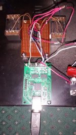
Oh, here is picture. You can see the DIYINHK USB board (green PCB) and then the flip flop (brown vero board). The Lundahls are on either side of the flip flop. AS I said, this is prototype only!!
And .... its sounding good. The flip flop has adressed the problems I had when the USB board was trying to drive the transformer directly. ie the bass is now at the correct level, and the overall output level is much higher (I had to turn amps up to 11 before, to get a normal listening volume).
I am listening to some recordings my audio buddy made through my Tascam DSD recorder. We have been recording LPs at DSD128, and playing these back right now -- wow, sounding very good.
The whole thing is only prototype and far from optimised. The power is from a computer SMPS, 5 volt output is going directly to flip flop and I am using a 3.3V reg between the 5V and the USB board. And the wiring - well I grew up wiring point to point, which is OK in valve amps maybe but in high speed digital circuitry - I am getting a fair bit of noise. But that's all OK, now I have something that works I can fine tune it because there is heaps of potential.
So I set out to build a DSD play back system without a DAC. I think that this is now working albeit with a flip flop instead of a DAC. I'd like to think that my way is better, but is this cheating? Is there an easier way to do this?
For now I will re-build my USB/DSD player and enjoy it. I'm sure I will think of some way to improve it, next week. In the meantime, I will start experimenting with Linux. And for something different I will play some records on my modified Lenco (which is waiting for even more modifications).
Oh, here is picture. You can see the DIYINHK USB board (green PCB) and then the flip flop (brown vero board). The Lundahls are on either side of the flip flop. AS I said, this is prototype only!!
Attachments
Well I have had some good results today..
Wow great result! Can you handscrible/draw up a diagram of what you've build?
I suspect a lot of how this thing is going to sound is based on the power supply.
If the flip-flop is wired to divide by two then you may be corrupting the DSD signal, but perhaps in a way which is not immediately obvious to the ear.hazard500 said:So I set out to build a DSD play back system without a DAC. I think that this is now working albeit with a flip flop instead of a DAC. I'd like to think that my way is better, but is this cheating? Is there an easier way to do this?
If the flip-flop is merely passing the signal on, then a single logic gate would do instead.
In either case you need a good supply rail for them, as you are listening to the supply rail modulated by the final gate and then low pass filtered (either explicitly or accidentally).
Wow great result! Can you handscrible/draw up a diagram of what you've build?
I suspect a lot of how this thing is going to sound is based on the power supply.
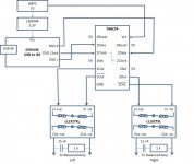
Certainly, I have drawn this up and attached the circuit.
Yes, power supply is critical. The 74HC74 can take up to 7 volts Vcc, I am thinking of a SLA. I use SLAs for my phono pre-amp and a 6 volt battery should do the job here. As for your other questions - I'm afraid I don't know enough about digital electronics to provide a definite answer. As far as I can tell from the spec sheet, output on the 74HC74 follows the input. I don't know why (or how) it would divide by 2. So as far as i can tell it does just pass the signal on. Would a single logic gate work? No idea. I don't know anything about logic gates except for what i have learned in the last 2 days!! But the critical thing is that 74HC74 has complementary outputs (in a digital sense) - in an analog sense, this means balanced output which is ideal for me. Would a single logic gate have complimentary outputs?If the flip-flop is wired to divide by two then you may be corrupting the DSD signal, but perhaps in a way which is not immediately obvious to the ear.
If the flip-flop is merely passing the signal on, then a single logic gate would do instead.
In either case you need a good supply rail for them, as you are listening to the supply rail modulated by the final gate and then low pass filtered (either explicitly or accidentally).
THanks to all for your input and questions. This has been a fun exercise for me and I have learned a lot. THis is exactly what DIY Audio is all about. Hopefully this thread will inspire some more experimentation.
Attachments

Seven volts is the "Absolute Maximun" rating, and that's not something recommended for normal operation The Fairchild data sheet I just pulled off the web shows a "recommended" range of 2 to 6 volts, and that's the range you'd want to stay within. There's also the concern of the DAC's output pin high and low voltages being compatible with the chip's input levels - these change with the power supply voltage as the data sheet shows, but they are most likely okay. My engineer mind wants to look to be totally sure.Certainly, I have drawn this up and attached the circuit.
Yes, power supply is critical. The 74HC74 can take up to 7 volts Vcc, I am thinking of a SLA.
I must say this is a neat circuit. (presumably the battery replaces the "SMPS" in the diagram which would be about the worse thing to power this with.
I'd also add a little (more) R/C filtering at the output, to prevent the ultrasonic and RF noise from going into the amp. Well, okay, in the earlier post you said these are going through transformers, and they will likely not pass much of the above-20kHz stuff.
In some configurations such a flip-flop circuit will divide the frequency of the input clock by 2, but not in this circuit.I use SLAs for my phono pre-amp and a 6 volt battery should do the job here. As for your other questions - I'm afraid I don't know enough about digital electronics to provide a definite answer. As far as I can tell from the spec sheet, output on the 74HC74 follows the input. I don't know why (or how) it would divide by 2.
If there's any concern, I'd want to see the timing of the DSD R/L/Clock signals from that other chip. It's possible for there to be a "race" condition where several things change at virtually the same time and an erroneous latch could occur. If so, fixing it would only need a 74HC series inverter between the DSD Clock output and the 74HC74 clock inputs.
You could make complementary outputs just using an inverter, but it has a delay and thus it would be different from the uninverted output. With a flip flop, the inverted and uninverted outputs change at the same time, after a small delay from when the clock input changes.So as far as i can tell it does just pass the signal on. Would a single logic gate work? No idea. I don't know anything about logic gates except for what i have learned in the last 2 days!! But the critical thing is that 74HC74 has complementary outputs (in a digital sense) - in an analog sense, this means balanced output which is ideal for me. Would a single logic gate have complimentary outputs?
THanks to all for your input and questions. This has been a fun exercise for me and I have learned a lot. THis is exactly what DIY Audio is all about. Hopefully this thread will inspire some more experimentation.
So I'm going backwards in the thread....
I am listening to some recordings my audio buddy made through my Tascam DSD recorder. We have been recording LPs at DSD128, and playing these back right now -- wow, sounding very good.
The whole thing is only prototype and far from optimised. The power is from a computer SMPS, 5 volt output is going directly to flip flop and I am using a 3.3V reg between the 5V and the USB board. And the wiring - well I grew up wiring point to point, which is OK in valve amps maybe but in high speed digital circuitry - I am getting a fair bit of noise. But that's all OK, now I have something that works I can fine tune it because there is heaps of potential.[/quote]
My suggested refinements are a small PCB with a large ground plane, and a 0.1uF cap right between the 74HC74 VCC and Gnd pins. And perhaps an extra R/C filter as I mentioned in the other post.
Who'd you buy it from? Mouser and Digikey have 'em for less than 50 cents each!!! 😀Well I have had some good results today. I bought a 74HC74 flip flop. It cost me $1.98 😉.
Part of this is the "balanced" output has 3dB higher signal, but from your description the transformer was excessively loading the original DSD output, and the 74HC74 outputs have greater drive capability.I have connected the output of the DIYINHK USBtoI2S board to the flip flop, and the complementary outputs of flip flop are connected directly to my Lundahl 1527XL transformers. I have a filter on the secondary of the tranny (15nF in series with 1k). And that's it. Sound is going straight to my balanced amps. Thanks to peufeu for the advice about the flip flop.
And .... its sounding good. The flip flop has adressed the problems I had when the USB board was trying to drive the transformer directly. ie the bass is now at the correct level, and the overall output level is much higher (I had to turn amps up to 11 before, to get a normal listening volume).
I am listening to some recordings my audio buddy made through my Tascam DSD recorder. We have been recording LPs at DSD128, and playing these back right now -- wow, sounding very good.
The whole thing is only prototype and far from optimised. The power is from a computer SMPS, 5 volt output is going directly to flip flop and I am using a 3.3V reg between the 5V and the USB board. And the wiring - well I grew up wiring point to point, which is OK in valve amps maybe but in high speed digital circuitry - I am getting a fair bit of noise. But that's all OK, now I have something that works I can fine tune it because there is heaps of potential.[/quote]
My suggested refinements are a small PCB with a large ground plane, and a 0.1uF cap right between the 74HC74 VCC and Gnd pins. And perhaps an extra R/C filter as I mentioned in the other post.
As far as terminology, the 74HC74 as used is arguably a "dual 1-bit DAC", and indeed a good power supply is critical because the PSRR here is 0 dB. Any variation of the 74HC74 Vcc line directly modulates the output.So I set out to build a DSD play back system without a DAC. I think that this is now working albeit with a flip flop instead of a DAC. I'd like to think that my way is better, but is this cheating? Is there an easier way to do this?
Last edited:
The PSRR is dependent on the flip-flop output state. For a logic '0' the PSRR is very good indeed, but for a '1' its 0dB as you say. Hence there's a signal dependent PSRR - aka noise modulation.
You're forgetting that it's a "digitally balanced" output. The signal is differential and across two outputs - one is always at ground while the other is always at VCC, and the amplitude is always the difference between them. The output gets modulated whichever state it's in.
Yep I hadn't picked up on that - I was only considering a single output pin of the HC74. So then the PSU noise will be added to the +ve phase for half the time and to the -ve for the other half of the time on average. So it looks to avoid noise modulation, assuming that the PSU noise is free of any correlation with the signal.
Certainly, I have drawn this up and attached the circuit.
.
Thanks, looks great. You wrote earlier you percieved the bass to be present. How about HF noise, some other none DAC DSD DAC's have been suffering from?
There's lots of noise, but that will be because:Thanks, looks great. You wrote earlier you percieved the bass to be present. How about HF noise, some other none DAC DSD DAC's have been suffering from?
1. I am still using a SMPS.
2. wiring is a rat's nest acting as an antenna (lots of antennas).
But its only a prototype. I need to now build a proper 'production' version with decent supply, proper wiring, grounding and shielding, before I can make any comments about noise. I enjoy the intellectual challenge of design, but I am not so good with construction - I am a big fan of point to point wiring and 'air boards'. So it may take me a while to get a proper build completed. But its fun listening to this right now even with all the noise, because the circuit you design yourself always sounds the best!!
No Mouer or Digikey in Australia - I use Jaycar. Just checked the catalogue, I misquoted price, they are only $1.25 each 🙂. But compared to a DAC - say a DIY sabre DAC such as the Buffalo (Twisted Pear) - well that will cost you at least $299 USD!!! I think my way is cheaper 😀.So I'm going backwards in the thread....
Who'd you buy it from? Mouser and Digikey have 'em for less than 50 cents each!!! 😀
My suggested refinements are a small PCB with a large ground plane, and a 0.1uF cap right between the 74HC74 VCC and Gnd pins. And perhaps an extra R/C filter as I mentioned in the other post.
I like your ideas on building out a production version. I will get onto it soon. Sooner or later. And whill update this thread with pictures.
Thanks hazard500, appreciate your sharing this and it'll be interesting to see where a more considered build takes it.
Can you add a little something to your diagram - the pins you're using on the LLundahl transformers. I'm assuming you're still using 1:1 series connection but would be good to confirm.
Are you still contemplating the Silk attenuator transformers you linked to back on page 1 of the thread? Volume control would be really handy.
If I can lay my hands on some suitable transformers I'm tempted to have a go with your circuit.
Ray
yes, tx is 1:1. Circuit diagram updated.Thanks hazard500, appreciate your sharing this and it'll be interesting to see where a more considered build takes it.
Can you add a little something to your diagram - the pins you're using on the LLundahl transformers. I'm assuming you're still using 1:1 series connection but would be good to confirm.
Are you still contemplating the Silk attenuator transformers you linked to back on page 1 of the thread? Volume control would be really handy.
If I can lay my hands on some suitable transformers I'm tempted to have a go with your circuit.
Ray
Silk transformers would be nice - but at USD450 its expensive. And switches are not included, so this would be an extra expense. Sowter also offers a similar product GBP140. Thats about half the price of the Silk tranny and Sowter is a highly regarded manufacturer. Usually manufacturing is outsourced to Thailand because its cheap (Ford Fiesta). It doesn't malke sense to buy from Thailand if it costs twice as much as a high quality European component. Unless I know that its twice as good. But I dont know this.
SOWTER ATTENUATOR TRANSFORMERS TVC VOLUME CONTROL
Attachments
Sorry, I jumped to a conclusion: that someone messing with digital electronics and choosing a flip-flop would know enough digital electronics to know what a flip-flop does (and what a logic gate does).hazard500 said:As far as I can tell from the spec sheet, output on the 74HC74 follows the input. I don't know why (or how) it would divide by 2. So as far as i can tell it does just pass the signal on. Would a single logic gate work? No idea. I don't know anything about logic gates except for what i have learned in the last 2 days!!
No, a logic gate has one output. However, it is trivial to arrange two suitable logic gates to get complementary outputs.Would a single logic gate have complimentary outputs?
You will still get noise IM, as it is the supply rail which sets the voltage gain of the output stage. The rail must be very clean, probably cleaner than usually required for normal analogue stages. Normal analogue stages have their gain loosely set by the supply rail; this analogue stage (yes, it is an analogue stage even though it uses 'digital logic') has its gain set directly by the supply rail.abraxalito said:So then the PSU noise will be added to the +ve phase for half the time and to the -ve for the other half of the time on average. So it looks to avoid noise modulation, assuming that the PSU noise is free of any correlation with the signal.
Many thanks hazard500 for starting this thread - I've been following it with interest.
Different 74HC74 chips seem to have different max output current (5.2mA or 25mA) and bandwidth (24-94MHz). All other things being equal, would you expect a high current and high bandwidth 74HC74 to be best?
Different 74HC74 chips seem to have different max output current (5.2mA or 25mA) and bandwidth (24-94MHz). All other things being equal, would you expect a high current and high bandwidth 74HC74 to be best?
- Home
- Source & Line
- Digital Line Level
- The Best DAC is no DAC