I think a potentiometer Is not the best way to achieve a volume control in that place.
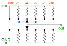
If you want a potentiometer, it must have a constant input impedance - eg a shunt ladder stepped attenuator.
If you use a simple potentiometer, every time you change volume you change the LPF -3dB frequency.
I don't think I said it was the best way, just that I did it - it actually worked very well.
I'm adding an analogue volume control to my current project and will be using a balanced 'U' shunt attenuator between the LP filter and the buffer input.
I think a potentiometer Is not the best way to achieve a volume control in that place.
If you want a potentiometer, it must have a constant input impedance - eg a shunt ladder stepped attenuator.
If you use a simple potentiometer, every time you change volume you change the LPF -3dB frequency.
Shunt attenuator (1 resistor) changes the LPF -3dB frecuency, ladder attenuator (2 resistors) not changes the LPF -3dB frecuency.
Attachments
Last edited:
Shunt attenuator (1 resistor) changes the LPF -3dB frecuency, ladder attenuator (2 resistors) not changes the LPF -3dB frecuency.
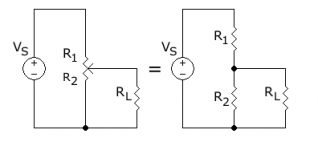
Now I'm confused. Thinking about this, wouldn't a 50K potentiometer always be a 50K load? Merlin's second diagram looks just like a potentiometer to me too - I'm assuming each pair or resistors always add up to the same total resistance so switching between pairs of resistors changes the potential divider ratio, just like a wiper in a pot?
Somebody educate me please
Last edited:
In the second graph the input impedance is always the same since always the sum of both resistances is equal (10K, 25K, 50K, etc depending your attenuator choice)
In the second graph the input impedance is always the same since always the sum of both resistances is equal (10K, 25K, 50K, etc depending your attenuator choice)
just like a potentiometer....
Attachments
just like a potentiometer....
Yes it's just a voltage divider.
So, going back to iperv's comment about my replacing the 47K fixed resistor with a 50K potentiometer, it worked OK because it is OK...
It's not the same: fixed resistor source and load sees the same impedance, potentiometer: source sees the same impedance but load don't sees the same impedance.
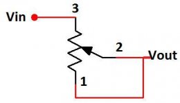
See attachment - regular potentiometer.
The best way is, of course, the ladder one.
EDIT:
With regular potentiometer R1 and R2 vary with volume changes, so Zin from source is:
R1+R2*RL/(R2+RL) = not constant.
EDIT2:
It is not a big problem due to the LPF (relative) high frequency.
Even if you change a little the Rin, frequency is always high enough to regular operation.
Attachments
Last edited:
It's not the same: fixed resistor source and load sees the same impedance, potentiometer: source sees the same impedance but load don't sees the same impedance.
How is that possible? both circuits are simple potential dividers, electrically the same. If they're electrically the same then they must behave the same.
See attachment - regular potentiometer.
The best way is, of course, the ladder one.
EDIT:
With regular potentiometer R1 and R2 vary with volume changes, so Zin from source is:
R1+R2*RL/(R2+RL) = not constant.
EDIT2:
It is not a big problem due to the LPF (relative) high frequency.
Even if you change a little the Rin, frequency is always high enough to regular operation.
Thanks iperv, I think your equation is the information I was missing. I'll run some values through that a bit later so I can see what is going on.
Ray
Isn't the same pot varies output impedance, fixed resistor not.
How?
Assume a fixed RL. If you have two potential dividers (#1 and #2) and at any given point, R1(#1) = R1(#2) and R2(#1) = R2(#2) then Zin(#1) must = Zin(#2), regardless of whether R1 and R2 are defined by a potentiometer or fixed value resistors.
Pot not varies the impedance seen by the source, pot varies the impedance seen by the load.
Amanero output is only 47 ohm.
But white noise i not like it.
But white noise i not like it.
What configuration of 'no-DAC' are you using after your Amanero? What music player software?
What configuration of 'no-DAC' are you using after your Amanero? What music player software?
I use jriver media.
Thanks
I use jriver media.
Thanks
Tell us about your low pass filter?
@vladimirb0b:
Hi ... It is a CR circuitry where - to my knowledge - the 47k resistor to ground and the input impedance of the subsequent circuitry (amplifier / preamplifier or ??) forms a parallel impedance. The capacitor in series with the signal then has a varying impedance depending on frequency (high pass) and thus sets a lower cut off frequency.
To my knowledge the formula for calculating this is identical to the formula for an RC filter (?) ... The difference being that the ordering of the active components leads to either a low pass (RC) or a high pass (CR) filter ...
@Ray: Thanks for the tip on the RC filter internet calculator. As it is I actually have set up an excel spreadsheet to calculate various calculations that I often need - including the RC filter results. But I appreciate the consideration ;-)
Cheers from Denmark,
Jesper
Quote:
Originally Posted by gentlevoice View Post
Hi Ray,
Just a brief comment: The formula for the cut off frequency for an RC circuit is 1 / (2*pi*R*C). Thus e.g. if the 22 uF capacitor in the JLSounds example looks into 10 kohms input impedance (e.g. pre-amplifier or amplifier) the cut-off frequency would be 0.7 Hz. With 2.2 uF the cut-off frequency is 7.234 Hz.
If I understand, what you are describing is a CR, not RC circuit. Gain should be close to zero unless you have a resistor in that path that would form a divider with the input impedance. If it didn't the audio signal would be lost any time there is a sizable capacitor parallel to the signal before any big resistance at all. Please correct me if I'm wrong.
v
Hi ... It is a CR circuitry where - to my knowledge - the 47k resistor to ground and the input impedance of the subsequent circuitry (amplifier / preamplifier or ??) forms a parallel impedance. The capacitor in series with the signal then has a varying impedance depending on frequency (high pass) and thus sets a lower cut off frequency.
To my knowledge the formula for calculating this is identical to the formula for an RC filter (?) ... The difference being that the ordering of the active components leads to either a low pass (RC) or a high pass (CR) filter ...
@Ray: Thanks for the tip on the RC filter internet calculator. As it is I actually have set up an excel spreadsheet to calculate various calculations that I often need - including the RC filter results. But I appreciate the consideration ;-)
Cheers from Denmark,
Jesper
- Home
- Source & Line
- Digital Line Level
- The Best DAC is no DAC