Amanero have develop a new firmware on Andrea Ciuffoli specification to eliminate the problem of the bump during pause and change tracks....
This is useful news for Amanero owners and, if my understanding is correct, it should address that boards shortcomings and put it's behaviour on a par with the JLSounds during playback. I believe both boards will still have the pop at Stop and Start, the magnitude of which will depend on the context in which they are being used.
If you're looking for a USB board for a no-dac project I would still recommend the JLSounds though because of its integrated isolation and reclocking.
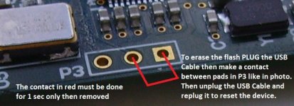
There's a useful guide to updating the Amanero here;
http://www.audiodesignguide.com/PureDSD/index.html
Ray
Last edited:
As a Windows user I have to disagree ,as the JLSounds windows driver is not licensed for DSD playback. There is a test Thesycon driver, which is cripled.
For Windows users the Wave IO board is the only board, I know of, which offers intergated isolation and a licensed DSD driver.
DIYinHK also advertises a isolated board, but I'm not sure their driver is genuine, they do say:"Fully featured Thesycon driver package"
For Windows users the Wave IO board is the only board, I know of, which offers intergated isolation and a licensed DSD driver.
DIYinHK also advertises a isolated board, but I'm not sure their driver is genuine, they do say:"Fully featured Thesycon driver package"
As a Windows user I have to disagree ,as the JLSounds windows driver is not licensed for DSD playback. There is a test Thesycon driver, which is cripled.
For Windows users the Wave IO board is the only board, I know of, which offers intergated isolation and a licensed DSD driver.
DIYinHK also advertises a isolated board, but I'm not sure their driver is genuine, they do say:"Fully featured Thesycon driver package"
Good point Stijn, I didn't factor in the operating system aspect and you're correct in that respect. As you know, I run a Linux NAA connected to my JLSounds, which requires no license.
I wasn't saying that the JLSounds is the only board offering isolation BTW, just that it is a plus point compared to the Amanero, worthwhile when you factor in their prices.
Ray
I'm trying to trim back on the number of projects I have on the go and have just posted this listing; it might suit someone looking for a tube-based no-DAC project.
http://www.diyaudio.com/forums/swap-meet/287528-fs-broskie-aikido-mfp-etc.html
Ray
http://www.diyaudio.com/forums/swap-meet/287528-fs-broskie-aikido-mfp-etc.html
Ray
@quanghao: Yes, very useful information indeed. Thanks for sharing!
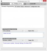
I just downloaded the 1.18 and seeing that there are quite some different CPU & flash options I wonder if I can ask you to share which CPLD & CPU firmwares are the "best" for DSD playback?
Thanks for any help in this ;-)
Jesper
This you can see all
thanks
Attachments
Hi all.
I don't remember the entire story...😀
Using DSD I have to say goodbye to - e.g. - all my dsp settings in JRiver - or equivalent player?
I ask this because I just build a pair of fullrange drivers based loudspeakers and they just need the convolver functions on JRiver - a simple dsp based baffle step correction.
They sound very good to my ears, so I'm planning on review my entire audio chain.
First step will be, of course, swapping from dac to dsd and now i'm afraid to loose the convolver functions.
Am I right?
@quanghao ... thank you very much Quanghao - this is exactly the information I was looking for ...
Cheers ;-)
Jesper
Cheers ;-)
Jesper
Hi! nautibuoy
in you usb and your ouput . Did you can hear the noise at the output?
thanks
Hi quanghao, there are two types of noise with this approach to DSD playback, white noise and pops/clicks, so I'll cover both.
On my first project (JLSounds/LP filter @40KHz, mute circuit, analogue volume control) the output was very clean with no audible white noise. very small pop/click when start or stop button pressed on music player (HQPlayer) and no pops/clicks between track changes.
On my recent project (JLSounds/flipflop/LP filter @80KHz, mute circuit/HQPlayer volume control) I could hear some white noise on the outputs and the pops/clicks at stop/start were louder. There are no pops/clicks between tracks. The white noise disappears if the HQPlayer volume control is disabled. I am currently reworking this project to use the revised mute circuit (with Fabio's addition) and to include an analogue volume control.
Ray
Hi nautibuoy
pops/clicks, ( this not problem ) . Thanks
i not ask you about this,
i want ask you about the output have some noise : EX
it resembles the sea waves.
or boiling water, but very little
you see them ??
thanks again
pops/clicks, ( this not problem ) . Thanks
i not ask you about this,
i want ask you about the output have some noise : EX
it resembles the sea waves.
or boiling water, but very little
you see them ??
thanks again
Hi nautibuoy
pops/clicks, ( this not problem ) . Thanks
i not ask you about this,
i want ask you about the output have some noise : EX
it resembles the sea waves.
or boiling water, but very little
you see them ??
thanks again
No, other than the white noise (which might be the same thing as you're describing) with the HQPlayer volume control engaged I have not experienced any audible noise on the outputs.
A bit like this;
https://www.youtube.com/watch?v=Y3FtM9M94SI
I could only hear the noise with the HQPlayer volume control engaged though. Miska gave some good info here;
HQ Player - Page 190
HQ Player - Page 190
Ray
https://www.youtube.com/watch?v=Y3FtM9M94SI
I could only hear the noise with the HQPlayer volume control engaged though. Miska gave some good info here;
HQ Player - Page 190
HQ Player - Page 190
Ray
Hi nautibuoy
other than the white noise
you can describe more clearly ??
thanks
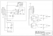
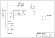
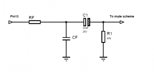
Attached are the schematics and BOMs for both the Balanced and SE boards.
For the SE board, it is worth a reminder that the board only has the LP filter components so you will need to consider DC blocking cap etc. arrangements depending on how you plan to use the boards. I have attached the original JLSounds simple filter schematic that started this whole thing off for info. I believe 22uF is a typo and a 2.2uF cap should suffice. (on my first build I used this original schematic but replaced the 47K0 resistor after the DC blocking cap with a 50K potentiometer to get a volume control.
Anyway, over to you...
Ray
Attachments
Hi Ray,
Although I'm not in on the group buy I think it's a very interesting thread & work you & others have done here ;-) ... looking forward to hearing the other members' feedback on how it sounds ...
Just a brief comment: The formula for the cut off frequency for an RC circuit is 1 / (2*pi*R*C). Thus e.g. if the 22 uF capacitor in the JLSounds example looks into 10 kohms input impedance (e.g. pre-amplifier or amplifier) the cut-off frequency would be 0.7 Hz. With 2.2 uF the cut-off frequency is 7.234 Hz. Many of you probably know this already so I just mention it.
Have a good weekend,
Jesper
Just a brief comment: The formula for the cut off frequency for an RC circuit is 1 / (2*pi*R*C). Thus e.g. if the 22 uF capacitor in the JLSounds example looks into 10 kohms input impedance (e.g. pre-amplifier or amplifier) the cut-off frequency would be 0.7 Hz. With 2.2 uF the cut-off frequency is 7.234 Hz. Many of you probably know this already so I just mention it.
There's a nice little calculator here if you want to avoid the maths...
Coupling Capacitor Calculator by V-Cap
Ray
Hi Ray,
Just a brief comment: The formula for the cut off frequency for an RC circuit is 1 / (2*pi*R*C). Thus e.g. if the 22 uF capacitor in the JLSounds example looks into 10 kohms input impedance (e.g. pre-amplifier or amplifier) the cut-off frequency would be 0.7 Hz. With 2.2 uF the cut-off frequency is 7.234 Hz.
If I understand, what you are describing is a CR, not RC circuit. Gain should be close to zero unless you have a resistor in that path that would form a divider with the input impedance. If it didn't the audio signal would be lost any time there is a sizable capacitor parallel to the signal before any big resistance at all. Please correct me if I'm wrong.
v
Last edited:
Attached are the schematics and BOMs for both the Balanced and SE boards.
For the SE board, it is worth a reminder that the board only has the LP filter components so you will need to consider DC blocking cap etc. arrangements depending on how you plan to use the boards. I have attached the original JLSounds simple filter schematic that started this whole thing off for info. I believe 22uF is a typo and a 2.2uF cap should suffice. (on my first build I used this original schematic but replaced the 47K0 resistor after the DC blocking cap with a 50K potentiometer to get a volume control.
Anyway, over to you...
Ray
I think a potentiometer Is not the best way to achieve a volume control in that place.
If you want a potentiometer, it must have a constant input impedance - eg a shunt ladder stepped attenuator.
If you use a simple potentiometer, every time you change volume you change the LPF -3dB frequency.
- Home
- Source & Line
- Digital Line Level
- The Best DAC is no DAC