For Clock distribution I just use TinyLogic Dual 04 (Inverter) / 16 (Non Inverters) as Clock buffers, I operate my array Logic at 5V - 6V for increased DNR.
If you operating with near 100MHz Clocks at 5V dont be caught out by the higher then expected power dissipation of CMOS logic.
I think you misread my question, or I did not make myself clear. I asked if this could be used between the Flip-Flop and the lowpass filter to ensure equal fall and rise times It was actually to prevent the RTZ circuit.
How about something like this:
https://www.idt.com/document/dst/5pb11xx-family-datasheet
Nice find koldby!
The equal rise and fall times are one side of the story. If the rise time would be, let's say, 1 fS and the fall time 2 fS I don't think we'd have this problem.
As long as 0110 has the same energy as 1010 (or 1001 etc) its oke, but it depends on what rate you're playing: i hardly hear funny noises @dsd64, but that's not our goal I assume;-)
You're the architect of what you're planning to achieve, that's the cool thing about this diy stuff.
I have actually made and measured the same circuit in balanced mode (Q and Q' as output) but with different flip flops (74HCT74 and 74AHCT74 and another fast 7474 but forgot the name) and the SE output were actually cleaner. It is only with the 74AUC1G that the results are this good. I guess that the Q and Q' are better matched and the output impedance in high and low state is better matched?
Did you use your battery as a supply at all times with these FF's, so the voltage was always somewhere between 3 and 4 volts?
I'm asking because hct needs 4.5 volts minimum, that might also explain your results.
I think you misread my question, or I did not make myself clear. I asked if this could be used between the Flip-Flop and the lowpass filter to ensure equal fall and rise times It was actually to prevent the RTZ circuit.
Oh Sorry, I did missread...
Its not a good device as it has internal 50 ohms termination resistors, as a DAC element, you really want the lowest output impedance (Also, the VC of these termination resistors will be poor).
However, in answer to your main point, it will not substitute a return to zero circuit.
Did you use your battery as a supply at all times with these FF's, so the voltage was always somewhere between 3 and 4 volts?
I'm asking because hct needs 4.5 volts minimum, that might also explain your results.
I've never had the best performance from HC / HCT logic - 74AC, 74VHC and UHS Tinylogic being the best.
I've not tired 74 LCX logic however...
Did you use your battery as a supply at all times with these FF's, so the voltage was always somewhere between 3 and 4 volts?
I'm asking because hct needs 4.5 volts minimum, that might also explain your results.
For the HCT and AHCT I used two LiFePo4 cells, so that was not the issue.
Why do I need an extremely low source impedance, when I have a 5-10 Kohm load?Oh Sorry, I did missread...
Its not a good device as it has internal 50 ohms termination resistors, as a DAC element, you really want the lowest output impedance (Also, the VC of these termination resistors will be poor).
However, in answer to your main point, it will not substitute a return to zero circuit.
The other thing is, that perhaps the different fall/rise time of the FF will just be reflected through the buffer.. Hmmm....
I guess the only way to avoid the RTZ is to find a FF with equal (or very low) rise and fall times.
Why do I need an extremely low source impedance, when I have a 5-10 Kohm load?
The other thing is, that perhaps the different fall/rise time of the FF will just be reflected through the buffer.. Hmmm....
I guess the only way to avoid the RTZ is to find a FF with equal (or very low) rise and fall times.
There is more to the Return To Zero circuit - I'll try to explain.:-
Lets image your PDM Data (DSD) has FOUR consecutive "Ones" in a row - after you latch the DSD Data, the first "One" will contribute the energy of a Rising edge + plus the remaining ON period, but the output will then stay HIGH for the remaining / next 3 ONES, so these will have no energy error due to the finite rising edge transition time (they just stay HIGH there is no Rising edge transition as the output is already HIGH from the proceeding Pulse(s)), with the final 4th pulse having a falling edge - So your four pulses contribute THREE different energy levels:-
1. First pulse has the energy contribution of the rising edge + the remaining "On" period.
2. Stays HIGH for Second pulse (no Edge transition)
3. Remains HIGH for Third pulse (no Edge transition)
4. Pulse Starts of HIGH (a continuation from the proceeding 3rd pulse) but has a falling edge transition "at the end of the Pulse period" as the output finally drops LOW.
So you can see that with the 4 pulses you contribute 3 different energy levels (even if the Rising and Falling edges have EXACTLY matched Rising / Falling edge speeds, the outputs have a small timing difference when they START to rise or fall - a real world Logic Gate does not behave perfectly symmetrical on the fS timescales that we require to meet for our Dynamic range performance target.
Also, due to finite edge transition times, any period with an edge transitions will contribute a different energy level to a Data (pulse) period WITHOUT a transition.
As each pulse MUST contribute an identical energy level, the only way to achieve this* is to insure a High / Low transition for EACH pulse - hence the requirement for RTZ "Modulation".
*Assuming a magical system with a perfect Clock / PSU etc.
I really hope my explanation helps to settle WHY RTZ is required for the highest measured performance - each and every DSD pulse High or Low must contribute an identical energy level...
Last edited:
@JohnW
That should settle it!
@MarcelvdG:
From your description of the RTZ circuit I'm taking that you have a Flip Flop'd datasignal and after that you apply the RTZ circuit. From there is it straight out (no other FF to take care of timing)?
I'm asking because I haven't tried but can imagine some simple logic having better phase noise/jitter than some FF's (shooting from the hip here;-). I always wondered about that, counterintuitive in a way since all data somewhere has to go through some FF, yet too many FF's also means routing many clock signals etc.
Your approach has one clear advantage and that is that one doesn't need a higher FClock.
@JohnW
In the same category I suppose:
The RTZ variant you describe needs really high clock speeds, 4 times the usual. Did you find or just decided that 50% more signal had more pro's than using a 2 times higher clock had con's? Why not go for an interleaved structure to mitigate the level drop? The logic you use seems well suited for this.
@All
Btw I really think this thread is awesome, if you don't mind me saying🙂
@MarcelvdG:
From your description of the RTZ circuit I'm taking that you have a Flip Flop'd datasignal and after that you apply the RTZ circuit. From there is it straight out (no other FF to take care of timing)?
I'm asking because I haven't tried but can imagine some simple logic having better phase noise/jitter than some FF's (shooting from the hip here;-). I always wondered about that, counterintuitive in a way since all data somewhere has to go through some FF, yet too many FF's also means routing many clock signals etc.
Your approach has one clear advantage and that is that one doesn't need a higher FClock.
Yes, that sums it up. Basically it's a D-flip-flop with a NOR gate and then a resistor.
For the complete circuits, see Very basic DSD ADC made with op-amps and logic gates and 74AHC02 and 74AHC08 DAC with 97 dB(A) dynamic range .
A clock buffer maybe? Are they not precisely enough?
I think the reason the 74AUC1G is performing so well is that when operating near its VCC limit, the rise and fall times are most equal and better that the other F-F I have tried.
I was terribly sloppy when I wrote about rise and fall times, because unequal rising and falling delays are just as bad. You need very good matching, I did a simulation once where the weight of the 1's changed by 0.1 % depending on whether the preceding bit was a 1 or a 0, this pretty much made the notches in the quantization noise spectrum invisible.
With a balanced circuit, in theory you get some cancelling between the errors of the non-inverted and the inverted outputs. Maybe the 74AUC1G has unusually good matching between its outputs.
The RTZ variant you describe needs really high clock speeds, 4 times the usual. Did you find or just decided that 50% more signal had more pro's than using a 2 times higher clock had con's? Why not go for an interleaved structure to mitigate the level drop? The logic you use seems well suited for this.
mterbekke,
Yes indeed I have a system MCLK of 2048fs (~100MHz), I see you understand how I'm generating a 1/4 RTZ period 🙂
Also, good question as to the Clock Phase noise, however the final pulse reputation rate is always the DSD "Bitclock rate", so my higher clock rate still benefits from the 20LogN division (Phase Noise reduction) from MCLK to DSD BCLK 🙂
Having a 100MHz clock operation also allows a 5th overtone oscillator circuit with its much higher Q... (And a nightmare to work with)... However the Phase noise advantage of ones 20LogN clock division hits a "limit" once you hit the thermal noise floor of the logic family, so at some point it no longer reduces with further clock division.
My Array structure is far more involved then I've discussed and I do interleave DAC elements etc. for various reasons - one of which is to reduce the common-mode modulation of the DAC array output voltage. I also have a truly balanced Master clock so I interleave the phasing of the DAC elements to null the MCLK rate (appreciating that the null depth is determined by the Clock phase matching - 40dB nulling is good going at 100MHz)!
WRT you question of the RTZ after simple NOR / NAND - yes it is preferable to Relatch to MCLK to reduce the phase-noise buildup though the logic gates.
With that said, I ALWAYS buffer the outputs of the latches to avoid "Integrated" Audio Ground return currents flowing though the shared Ground pin on the Latch. My thinking is that a Logic Inverter is the simplest Logic Gate (used as a buffer) and hence adds the lowest phase noise to the Latch output. Certainly its preferable to having the "Integrated" Audio return currents flowing though your synchronization device (Latch).
With the Dacapo which was a discrete DAC I designed back in 1990 (I believe the works first discrete 1bit DAC design???), due to my inexperience at the time (I was 19 when I designed the Dacapo) I did not re-synchronize the outputs after the simple RTZ circuit - but many (including myself) still consider it as one of the best sounding DAC's... It certainly decimates the sound quality of my later designs using ESS Sabre DAC's!! talk about going backwards over time as a designer!!
This is one of the reason I've given up on ESS based designs and back to fully discrete DAC designs... 🙂 its certainly harder (but way WAY more fun to design) - not to mention the sound quality is in a different league!
Last edited:
WRT you question of the RTZ after simple NOR / NAND - yes it is preferable to Relatch to MCLK to reduce the phase-noise buildup though the logic gates.
That seems illogical to me. If the RTZ circuit works the way it is supposed to, the delay from the clock to the RTZ circuit's output is only determined by the logic gate, not by the flip-flop or by anything else. Why would having a latch be preferable to having just a NOR gate?
That seems illogical to me. If the RTZ circuit works the way it is supposed to, the delay from the clock to the RTZ circuit's output is only determined by the logic gate, not by the flip-flop or by anything else. Why would having a latch be preferable to having just a NOR gate?
Its not related to "Delay" but the additional phase noise of the logic gate - the output of this extra logic gate is not synchronized to the clock - which is why it is a good idea to resynchronize the RTZ formatted Data to MCLK, this way your back to the Phase noise of JUST the Latch not Latch + Gate in series.
To put it in a different way, the output of the RTZ circuit is a simple Asynchronous circuit, its Phase noise is a simple logic function of BOTH the DATA and Clock inputs where as in an idealized world the output Phase noise of a Latch* is ONLY determined by the Phase noise on its clock input. In simplistic terms as a Clock Synchronized logic device a D-type FF has only one input (port) that effects its output phase noise - its Clock input.
* As long as the Latch Setup and hold times are met, and thinking in simple Digital Logic terms (not factoring real world "Analogue" characteristics of a logic device - but these apply equally to both the FF Latch and simple Gates).
I understand why mterbekke posted the question and he is correct in his reasoning WRT final phase noise of the DAC output IMO - in fact by asking such pointed questions mterbekke has an understanding of the atleast some of the challenges of designing a discrete DAC 🙂
Last edited:
Well, I think it all has to do with where in theory you think your time data reference comes from, and in the end that's the oscillator together with a FF somewhere, right?!
It doesn't really matter if and's, nand's or nor's don' t do much harm to the integrity of the signal if you decide that a FF delivers the only real reference in the dac. Where else could that highest level of signal integrity be if you decide (can only admit it originates) the FF delivers it?
The only way out of this is if there's something off theoretically (e.g a FF might do more harm because the less than ideal power supply implemented, which could by chance be mitigated by e.g. an And) , or if the measurements are disproving one's ears:
one might think this by missing of the tapping of the foot, or loss of image depth etc etc.
Now that proof of the ears thing is a can of worms.
I have been proven wrong on just enough occasions just looking at data alone. Then again: most breakthroughs have been by using the right measuring equipment together with gained insight as well and had breakthroughs by chance and didn't measure afterwards.
It all matures how one comes to a dac and most of the time measuring and listening for proof go hand in hand.
Particularly I find the part about the ground return points of interest, as it illustrates nicely how all things connect together and what should be left out of the equation (RF signals are nasty when you want to extract delicate analog signals from it), It shows great attention to detail, and that many things that are easy to overlook to have a good look at. This takes years. Above all it shows you might hit a rock in development and to overcome you need a different way of looking at things to overcome the obstacle.
In the end, curiosity, experience and "standing on shoulders of giants" is what brings us closer to our music. Having said all that, I think it's time I should hop over to the bar because I guess that's where my head is at already ;-)
Cheers and G'night!
Last edited:
RTZ implementation
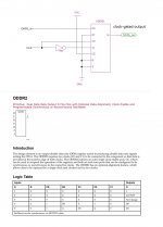
If you want to design RTZ signal in FPGA, "clock gate" is usually inhibited because the clock is dedicated to drive clock input only to ensure low jitter and skew. 100MHz clock with more than 1000 fanouts is ordinary in FPGA design. Instead, double clock rate or DDR FF is used to make RTZ. Double clock (2x100MHz) ends up high power consumption. DDR FF is better for RTZ like the attached pic since the double rate is local.
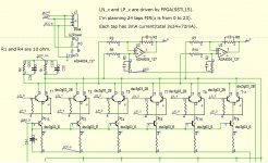
BTW, I'm now designing DA converter(no DAC chip) for 1bit DSM. No DAC topology usually has 0 PSRR, which is the disadvantage of no DAC. I tried ECL logic conversion to have some PSRR before. I wasn't able to have a good result because it had only one tap, and the driver was poor. My current design has 24 taps and a powerful driver, e.g., SSTL15 designed for DDR3(up to 800MHz). My PCM to DSM conversion implemented by FPGA is already finished. The rest to the goal is ideal PA conversion, I would say Pulse to Analog, in 1bit DSM. How about the attached pic?
If you want to design RTZ signal in FPGA, "clock gate" is usually inhibited because the clock is dedicated to drive clock input only to ensure low jitter and skew. 100MHz clock with more than 1000 fanouts is ordinary in FPGA design. Instead, double clock rate or DDR FF is used to make RTZ. Double clock (2x100MHz) ends up high power consumption. DDR FF is better for RTZ like the attached pic since the double rate is local.
BTW, I'm now designing DA converter(no DAC chip) for 1bit DSM. No DAC topology usually has 0 PSRR, which is the disadvantage of no DAC. I tried ECL logic conversion to have some PSRR before. I wasn't able to have a good result because it had only one tap, and the driver was poor. My current design has 24 taps and a powerful driver, e.g., SSTL15 designed for DDR3(up to 800MHz). My PCM to DSM conversion implemented by FPGA is already finished. The rest to the goal is ideal PA conversion, I would say Pulse to Analog, in 1bit DSM. How about the attached pic?
Attachments
Its not related to "Delay" but the additional phase noise of the logic gate - the output of this extra logic gate is not synchronized to the clock - which is why it is a good idea to resynchronize the RTZ formatted Data to MCLK, this way your back to the Phase noise of JUST the Latch not Latch + Gate in series.
To put it in a different way, the output of the RTZ circuit is a simple Asynchronous circuit, its Phase noise is a simple logic function of BOTH the DATA and Clock inputs where as in an idealized world the output Phase noise of a Latch* is ONLY determined by the Phase noise on its clock input. In simplistic terms as a Clock Synchronized logic device a D-type FF has only one input (port) that effects its output phase noise - its Clock input.
* As long as the Latch Setup and hold times are met, and thinking in simple Digital Logic terms (not factoring real world "Analogue" characteristics of a logic device - but these apply equally to both the FF Latch and simple Gates).
I understand why mterbekke posted the question and he is correct in his reasoning WRT final phase noise of the DAC output IMO - in fact by asking such pointed questions mterbekke has an understanding of the atleast some of the challenges of designing a discrete DAC 🙂
This still doesn't make any sense to me. The way logic gates, latches and flip-flops can worsen jitter is by small random variations of their delay (due to noise, supply ripple or whatever). Hence, any delay that is not in the path from clock to output does not worsen the jitter.
If you design your RTZ circuit properly, the clock and the delay of the logic gate determine when the output switches. The data coming from the flip-flop switch at moments when the gate is not sensitive anyway, because the other input determines its output level.
BTW, I'm now designing DA converter(no DAC chip) for 1bit DSM. No DAC topology usually has 0 PSRR, which is the disadvantage of no DAC. I tried ECL logic conversion to have some PSRR before. I wasn't able to have a good result because it had only one tap, and the driver was poor. My current design has 24 taps and a powerful driver, e.g., SSTL15 designed for DDR3(up to 800MHz). My PCM to DSM conversion implemented by FPGA is already finished. The rest to the goal is ideal PA conversion, I would say Pulse to Analog, in 1bit DSM. How about the attached pic?
At first I thought the names of the transistors were automatically generated (DSC version 3, gen 03), but it turns out they're actual transistors. What a coincidence!
I thought about doing something similar to ensure voltage swing as well as having great speed and true current outputs etc. I thought matching of the transistors would be important as well as exact placement and thermal coupling between the parts. Seems really difficult to do well.
What made you abandon the ecl logic, too much noise, distortions...?
This still doesn't make any sense to me. The way logic gates, latches and flip-flops can worsen jitter is by small random variations of their delay (due to noise, supply ripple or whatever). Hence, any delay that is not in the path from clock to output does not worsen the jitter.
If you design your RTZ circuit properly, the clock and the delay of the logic gate determine when the output switches. The data coming from the flip-flop switch at moments when the gate is not sensitive anyway, because the other input determines its output level.
Well, which part is in your eyes the one with the lowest jitter (and causes more delay): is it directly at the output of the flip flop or the output of the added gates behind that flip flop? This seems logical because with the RTZ circuit after the FF you'd have to add both jitters (FF + RTZ) to the signal when having the FF as the last part means 1 less jitter added.
I also suspect I don't really get what you mean because this is so obvious.
As far as data or clock feedthrough go: I suspect that's one of the reasons why source jitter before a FF still can be measured even when setup times are met.
Well, which part is in your eyes the one with the lowest jitter (and causes more delay): is it directly at the output of the flip flop or the output of the added gates behind that flip flop? This seems logical because with the RTZ circuit after the FF you'd have to add both jitters (FF + RTZ) to the signal when having the FF as the last part means 1 less jitter added.
I also suspect I don't really get what you mean because this is so obvious.
Yes, I'm also struggling with this...
As far as data or clock feedthrough go: I suspect that's one of the reasons why source jitter before a FF still can be measured even when setup times are met.
Yes, very much so!!! You need to consider the "Analogue" characteristics of a logic gate when used in our sudo Digital / Analogue mode of operation.
Just as a Switch or Relay does not give perfect off isolation, a FF has non linear jitter isolation - where the the jitter is "significantly reduce upto a point where the device parasitic comes into play.
The most significant "parasitics" of a device are:-
1. Device pinning - FF normally have Date and Clock pins adjacent to each other so that they couple with each other.
2. Shared Ground return paths for the devices Input and Outputs
3. Internal PSU impedance - internal circuit sections modulate each other
I measured Jitter attenuation of a 74AC74 at 100MHz to only be about 30dB to 40dB...
I'm not sure how to best describe the Jitter attenuation "non linearity" - essentially 1ns of jitter is reduced to almost the same level as would 10nS of Jitter - to a point where the device parasitic comes into play and then starts to dominate....
Different logic families (and manufactures) have very different results, hence the differences in sound quality of logic gates in our sudo digital / analogue application 🙂 Arh don't you love the word "Digital" when it is any but!!!
- Home
- Source & Line
- Digital Line Level
- The Best DAC is no DAC