add solder to all pins from bottom side , heat all 3 pins together , pull them
suck or wick solder from holes later
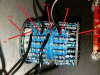
Thanks, adding solder is counter-intuitive but it worked. I installed new MOSFETs but have a different problem now. One side biased up fine, the other has high voltage across R10 and R11. I've been over the circuit with a fine-tooth comb and can't see anything wrong. Pots are at zero ohms.
Good side:
Whole board:
Any ideas?
Well done Mark. Looking at the photo you have posted of the complete PCB, can I suggest you fit some insulated sleeving over the leads on C3 electro caps, in case the lead wears through the solder mask and shorts out on PCB tracks on top layer - just a precaution.
Well done Mark. Looking at the photo you have posted of the complete PCB, can I suggest you fit some insulated sleeving over the leads on C3 electro caps, in case the lead wears through the solder mask and shorts out on PCB tracks on top layer - just a precaution.
Great advice, thanks.
Now I'm trying to get sound out of it and I don't think I have the stepped pot right. I bought this one:
4pole 24 Step Attenuator Volume Control Pot Log A 25K 25KA Stereo Potentiometer | eBay
and it doesn't have a ground connection like the Glassware one in Jim's, and I just bypassed the ground signal wire. Do I need to connect ground to the pot?
4pole 24 Step Attenuator Volume Control Pot Log A 25K 25KA Stereo Potentiometer | eBay
and it doesn't have a ground connection like the Glassware one in Jim's, and I just bypassed the ground signal wire. Do I need to connect ground to the pot?
Yes Mark, you need Input, Output (wiper on a normal pot) and GND connection for each channel. The ebay seller should be able to supply you with a drawing or photo with clearly shown connection details for each of the 6 connections for stereo operation.
What would be the 24th hole on the outer ring is clearly marked ground (GND). You could try connecting there.
You can also see the GND point on the other ring in the other photo, but it will also be wise to check the connections for input and output. A DMM will help work that out as well. One lead of the DMM on resistance scale applied to the GND point and the other lead on where you think you have the input wire should read a constant 25000 ohms, then moving that lead to the output connection and turning the shaft should then show a varying resistance from zero ohms at the minimum shaft position up to 25000 ohms at the maximum shaft position - you wont get a constant resistance reading as you switch from one position to the next due to the logarithmic affect of the resistance array.
You have also shown the link to a 25K attenuator, Nelson has the volume pot on the output of the BA3 design as a 5k attenuator (pot) or are you putting this 25 K attenuator on the BA3 input?
You have also shown the link to a 25K attenuator, Nelson has the volume pot on the output of the BA3 design as a 5k attenuator (pot) or are you putting this 25 K attenuator on the BA3 input?
Now I'm trying to get sound out of it and I don't think I have the stepped pot right. I bought this one:
4pole 24 Step Attenuator Volume Control Pot Log A 25K 25KA Stereo Potentiometer | eBay
and it doesn't have a ground connection like the Glassware one in Jim's, and I just bypassed the ground signal wire. Do I need to connect ground to the pot?
I used those in both my BA3 FE jobs. Quiet as a mouse. I just hooked it up.
Only grounds I used went to BA3 board as I recall. I always have trouble "seeing" preamp switching and volume knob wiring...going through that now with the DCG3 Preamp....
Russellc
Well done Mark. Looking at the photo you have posted of the complete PCB, can I suggest you fit some insulated sleeving over the leads on C3 electro caps, in case the lead wears through the solder mask and shorts out on PCB tracks on top layer - just a precaution.
Most here have used 25K to 50K on these builds. 6L6 in this build guide used a 50K Goldpoint. See second pic and writing underneath in post #1
Russellc
Here you go.......
most likely as attached
in worst case , you'll need to swap IN and OUT leads
anyway , IN points are shorted to GND when switch is all the way CCW
Attachments
Thanks all, it is on the BA-3 input side, as this how I saw 6L6's wired at the beginning of the thread but maybe I'm mistaken?
I'll work on it this morning!
I'll work on it this morning!
- Home
- Amplifiers
- Pass Labs
- The BA-3 as preamp build guide