This one is also neat: BJT cascoded drivers with zeners and MOSFET cascodying the outputs.
Edit: actually, this one can use 6V2 for the drivers...
Edit: actually, this one can use 6V2 for the drivers...
Attachments
Last edited:
This is better.
I added current mirror "help" in the form of a diode (as Bimo has it) but I don't see much improvement. I added my "buffer" for the current output of the input section. Again, no much improvement here.
You know I am a nullity. Please, anybody can swap my International Rectifier MOSFET for some laterals, like Toshiba 2SK1058/2SJ162, with models, in the following .asc file?
I would be very grateful. 🙂
Attachments

I believe IRFP240/IRFP9240 MOSFETs complemmentary pairs should do well as cascodying elements for the outputs. With a VGS of around 4V, 8V2 zeners would do OK. I got the models. Lets see if I can make them work...
I know how to load models on the working sheet, but how do I make them appear on the selection list of the simulator? 😕
With these MOSFETs, it shall be easy to make higher power Amnesis amp with paralleled outputs...I still have 60V and 72V supplies here. 😎 😀
I hope some news about further success today.
Cheers,
M.
PS: does anybody know a complementary pair of Depletion mode power MOSFETs to evaluate as cascodying element???
(That doesn't cost an arm and a leg...)
Last edited:
Hi Max,
your latest circuit has some interesting features, not sure I understand the advantage of diode D17, but it improves that sound thats good.
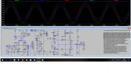
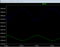
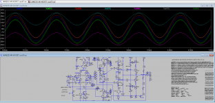
Meanwhile, when I ran the simulation and noticed the current in the input stage R13 and R19 shows two worrying issues see the screen shot.
1. the currents are not in balance I'd expect the waveforms to be on top of each other.
2. the spikes at the peaks suggest there is switching noise probably due to under biased output stage.
For the second issue changing value of R23 from 1K to 1.2K seems to take care of the switching noise, and gets rid of the high freqency hash in the FFT.
I look forward to further reports.
Symon
your latest circuit has some interesting features, not sure I understand the advantage of diode D17, but it improves that sound thats good.
Meanwhile, when I ran the simulation and noticed the current in the input stage R13 and R19 shows two worrying issues see the screen shot.
1. the currents are not in balance I'd expect the waveforms to be on top of each other.
2. the spikes at the peaks suggest there is switching noise probably due to under biased output stage.
For the second issue changing value of R23 from 1K to 1.2K seems to take care of the switching noise, and gets rid of the high freqency hash in the FFT.
I look forward to further reports.
Symon
Attachments
Dear friends, this is maxlorenz, your humble narrator (BTW, Stanley Kubrik would have been celebrating his birthday recently, provided he didn't have shot his last film...) bringing the good news.
Ladies and Gentlemen, Mesdammes et Messieurs, Damy i Gospoda, and the new!!! Oh, sorry, to much boxing latelly. 😀
I think we have a definitive winner. 😎
You cannot say I did not do my homework...let me recapitulate: I had a terrible problem with the bias of my cascode output. It clipped heavilly with the low Vsource for the base of the cascode BJT cascode element. Only a 15V swing, peak to peak for 32V PS...no big problem if you only need, like me, just a couple of watts (and I don't see how could anybody need more...) but that circuit was not presentable in a respectable forum like our beloved DIYaudio...
So, four plans were presented, namelly:
1) external floating Vsource.
2) local active Vsource.
3) passive Vsource feeding MOSFETs.
4) autobias with VFETs.
By now you probably know me: I went for the more complicated first. Numbers 1 and 2 did work but introduced heavy oscillation on the negative peaks 🙁 as before...I tried some tricks but finally gave up.
Fortunatelly I found here some IRFP240. I did not find IRFP9240 but I had other MOSFETs around, so I went for the easiest mod on paper. I posted already the circuit, with different units. I used a 2K5/2W resistor equivalent and 7V5 zeners plus one diode to make for the lack of 8V2 zeners. Dear friends: it worked. I had good luck with IRF5210 as P channel MOSFET. The VCE for the output BJT is now between 4.5V and 4.7V (IRFP240's side) and -4.5V and -5.1V (IRF5210's side), which depends on zener and MOSFET variabiity, I imagine. Pease see post #162.
I could not make it to clip until the collapse of the power supply...I confess though I still had my 200W light bulb in series...
Anyway, I am ordering a bunch of 8V2 zeners and IRFP240/9240 MOSFETs.
Soon I will publish the first Official Amnesis schematics...which then will be probably heavilly modded... 😀
Dear Symon, I was totally busy as you see, so I will answer you later, IF I have something intelligent to say...🙂
Many thanks again to everyone who helped, critiqued, defied, encouraged, worried...etc.
God bless you all.
M.
Last edited:
Hello maxlorenz,
it's good to hear that you found a practicable solution with a low complexity
for cascoding the outputs. Congratulations!!!!
Since I have the time to update my layout proposal acc. to your latest findings
I have some questions/proposals:
The cascoding transistors for the driver stage need to be mounted on heat sink now. I propose to mount them together with driver transistors on the same heat sink (e.g. T-/L-Profile). If mounting one transistor to the left side and the other to the right side the profile gets mechanical stability without further fixation to the PCB. The seize of the profile can easily be determined by the thermal requirements.
driver transistors: are still 2SC4793/ 2SA1837 your favorites?
cascode transistors: BD139/BD140 ???
Are the resistors R64/R66=50R between driver and cascode necessary??
Could you already find out whether the bootstrapping version is still your favorite or is the CCS solution acc. to your latest simulation schematic a serious alternative.
I'll soon post a layout update with the latest output stage.
Hi JOSI1,
Thanks very much.
I'm on a hurry so wait for my later reply...I was thinking of updating you with the same topics! Common sense will determine the changes.
See you.
M.
Thanks very much.
I'm on a hurry so wait for my later reply...I was thinking of updating you with the same topics! Common sense will determine the changes.
See you.
M.
Dear Symon,
That diode is simulated, not tested in real life yet. Perhaps Bimo could explain the goods...
I confess I still don't know how to see those currents plotted...
The voltages are on phase, though. Maybe is my experimental buffer doing strange things.
Yes, the experimental buffer for the output of that diff. pair perhaps loads it excessivelly. It seems to improve slightly the THD numbers, though.
The peaking dissappears without the PNP buffer, which I did not test yet in real life. You are right about the effect of increasing R23 but this also increases current bias for the outputs so one has to factor for this into the game. I'll play a little with the simulations.
Dear JOSI1,
That seems a good idea and probably saves space. In fact I did the same in my first Amnesis/Blame.
Now that we plan to cascode as depicted with 6V2 Zeners, the drivers will get an easy life so it is better to use small ones (lower Cob) like BD139/140 as drivers. Remember they have inverted pinout compared to almost every other BJT.
Now, the cascode transistors will have harder life, with 44V on a 50V supply, if someone wants to give that option a try. So it is better to chose a medium size BJT, with better thermal resistance. I used 2SC4793/ 2SA1837 because I bought a bunch of them on eBay and they have plastic body so they are easy to mount on heat-sink. They are working great on the experimental amp. The bigger capacitance of the bigger BJT does not matter on common-base configuration.
Having said that, I believe any good driver would be OK here, even repeating BD139/140. Maybe some mates could give advice.
Please note that I had not the time to evaluate if this mod makes a sonic improvement. It would be easy, though, to make sonic comparisons on the PCB or someone could chose to build a simple driver version.
They are not essential. Last time I checked, they made a slight improvement on THD. I will re-check and I recommend you do the same for any doubts that may arise. Edit: marginal changes in 2nd and 4th harmonics. Can be safely erased.
BTW, how do I increase the number of harmonics evaluated on the THD analysis on LTspice???
Tonight I plan to make some listening tests/comparisons, but, as I said, it is easier to transform a CCS-loaded VAS into a bootstrapped VAS than the other way around. So maybe it is wise to go for the CCS-loaded VAS.
Yet, the schematic for the bootstrap looks so less congested. Perhaps I can leave the minimum of bypass caps...
There are a couple of differences between my real bootstrap and the CCS-loaded VAS amps anyway: linear "charge-transfer" supply v/s SMPS with augmented capacitance; BJT v/s MOSFET cascode for the outputs.
Anyway, the listening test will be on normal listening volumes...perhaps when someone tortures the amp we may find a problem needing fixing 🙁 hey but that is the joy of DIY 😀
BTW, those big resistors (bootstrap and cascode) better be 3W as simulations say some must tolerate 630mW. Better have some clearance from PCB also. The zeners should be OK but one can also parallel a couple of them, just in case.
Edit: upload for the AMNESIS BOOTSTRAP cascoded emitter follower with MOSFET. I hope I did not too many mistakes.
Best wishes,
M.
your latest circuit has some interesting features, not sure I understand the advantage of diode D17, but it improves that sound thats good.
That diode is simulated, not tested in real life yet. Perhaps Bimo could explain the goods...
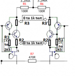
Meanwhile, when I ran the simulation and noticed the current in the input stage R13 and R19 shows two worrying issues see the screen shot.
1. the currents are not in balance I'd expect the waveforms to be on top of each other.
I confess I still don't know how to see those currents plotted...
The voltages are on phase, though. Maybe is my experimental buffer doing strange things.
2. the spikes at the peaks suggest there is switching noise probably due to under biased output stage.
For the second issue changing value of R23 from 1K to 1.2K seems to take care of the switching noise, and gets rid of the high freqency hash in the FFT.
Yes, the experimental buffer for the output of that diff. pair perhaps loads it excessivelly. It seems to improve slightly the THD numbers, though.
The peaking dissappears without the PNP buffer, which I did not test yet in real life. You are right about the effect of increasing R23 but this also increases current bias for the outputs so one has to factor for this into the game. I'll play a little with the simulations.
Dear JOSI1,
The cascoding transistors for the driver stage need to be mounted on heat sink now. I propose to mount them together with driver transistors on the same heat sink (e.g. T-/L-Profile). If mounting one transistor to the left side and the other to the right side the profile gets mechanical stability without further fixation to the PCB. The seize of the profile can easily be determined by the thermal requirements.
That seems a good idea and probably saves space. In fact I did the same in my first Amnesis/Blame.
driver transistors: are still 2SC4793/ 2SA1837 your favorites?
cascode transistors: BD139/BD140 ???
Now that we plan to cascode as depicted with 6V2 Zeners, the drivers will get an easy life so it is better to use small ones (lower Cob) like BD139/140 as drivers. Remember they have inverted pinout compared to almost every other BJT.
Now, the cascode transistors will have harder life, with 44V on a 50V supply, if someone wants to give that option a try. So it is better to chose a medium size BJT, with better thermal resistance. I used 2SC4793/ 2SA1837 because I bought a bunch of them on eBay and they have plastic body so they are easy to mount on heat-sink. They are working great on the experimental amp. The bigger capacitance of the bigger BJT does not matter on common-base configuration.
Having said that, I believe any good driver would be OK here, even repeating BD139/140. Maybe some mates could give advice.
Please note that I had not the time to evaluate if this mod makes a sonic improvement. It would be easy, though, to make sonic comparisons on the PCB or someone could chose to build a simple driver version.
Are the resistors R64/R66=50R between driver and cascode necessary??
They are not essential. Last time I checked, they made a slight improvement on THD. I will re-check and I recommend you do the same for any doubts that may arise. Edit: marginal changes in 2nd and 4th harmonics. Can be safely erased.
BTW, how do I increase the number of harmonics evaluated on the THD analysis on LTspice???
Could you already find out whether the bootstrapping version is still your favorite or is the CCS solution acc. to your latest simulation schematic a serious alternative.
Tonight I plan to make some listening tests/comparisons, but, as I said, it is easier to transform a CCS-loaded VAS into a bootstrapped VAS than the other way around. So maybe it is wise to go for the CCS-loaded VAS.
Yet, the schematic for the bootstrap looks so less congested. Perhaps I can leave the minimum of bypass caps...
There are a couple of differences between my real bootstrap and the CCS-loaded VAS amps anyway: linear "charge-transfer" supply v/s SMPS with augmented capacitance; BJT v/s MOSFET cascode for the outputs.
Anyway, the listening test will be on normal listening volumes...perhaps when someone tortures the amp we may find a problem needing fixing 🙁 hey but that is the joy of DIY 😀
BTW, those big resistors (bootstrap and cascode) better be 3W as simulations say some must tolerate 630mW. Better have some clearance from PCB also. The zeners should be OK but one can also parallel a couple of them, just in case.
Edit: upload for the AMNESIS BOOTSTRAP cascoded emitter follower with MOSFET. I hope I did not too many mistakes.
Best wishes,
M.
Attachments
Last edited:
Are the resistors R64/R66=50R between driver and cascode necessary??
They are not essential. Last time I checked, they made a slight improvement on THD. I will re-check and I recommend you do the same for any doubts that may arise. Edit: marginal changes in 2nd and 4th harmonics. Can be safely erased.
Man, what was I thinking when I wrote that sh**t!
This thread is not about THD. Lets keep the capacity for the optative resistor in true DIY spirit. The recommended way to do the experimentation willl be: simple driver-->cascoded driver--> cascoded driver plus emitter to collector resistor.
It is hard to tell what version is better. See the caveat above...
I believe neither will dissapoint. And we all can then forget about this THD nonsense... 😀 Time domain is more important than frequency domain.
Lets go for the CCS-loaded Hawksford cascoded VAS. As I said, anybody can perhaps use the holes for the Miller cap instead for the boostrap cap and use a jumper from feedback path to negative pole of the said cap then a couple of 1k power resistors: 1 from from (+) rail to bootstrap node; another from that node to Vbe multiplier positive node input...and voilá! Bootstrapped VAS.
I've been thinking a lot about the cascode...a mate of us, one of our watchers that always commes to the rescue of us, lost souls, commented "cascode is no magic"...that picked me a little as I do think there is some sort of magic to the combination...I'll try to elaborate further when I have time.
Yours trully,
M.
PS: go and buy some IRFP MOSFETs before I monopolize the world stock!
Attachments
Last edited:
You are right about the effect of increasing R23 but this also increases current bias for the outputs so one has to factor for this into the game. I'll play a little with the simulations.
Talking about bias current, with the new configuration the main output transistor gets a +/- 4.5VCE, equals easy (well under SOA) life and the current for the MOSFET is determined by the former, so I think it is safe to increase bias current, guided by the simulated behavior on FFT and Bode plots, and later, by sonics...am I right?
Best regards,
M.
PS: those TO-247 MOSFETs are good looking...
Last edited:
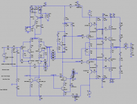
And this would be the recommended Amnesis Bootstrapped VAS with MOSFET cascode.
Note that it is stable and produces decent THD even at higher bias current and near clipping, with 1.3V signal.
While 6V2 zener would do for the drivers' cascode circuit, I noticed that 8V2 zeners also work well and with even lower THD, mainly pair integer harmonics, for those who care.
Cheers,
M.
Note that it is stable and produces decent THD even at higher bias current and near clipping, with 1.3V signal.
While 6V2 zener would do for the drivers' cascode circuit, I noticed that 8V2 zeners also work well and with even lower THD, mainly pair integer harmonics, for those who care.
Cheers,
M.
Attachments
OK. A couple more hours of listening to the Amnesis with MOSFET cascode.
I now confess I was prejudiced negatively towards those IRFP units from a former experience with my clone of a famous SIT amp whose name shall remain secret but which ends with a "2". 😀 I used the IRFP240 as CCS on that one. It sounds good but not great...
This version of the amp sounds robust to say the least, with ample bass and rotund midrange. In fact I had to re-set the selector of my "midrange presence" on the old ESS Heil tweeter crossover from "increase" to "flat" to be able to tolerate it...transparency and highs (which are sweeter though) suffered, compared to the BJT version, but this could be a question of "burn-in" or maybe it is time to connect the magic RDRD string on the output... 😉
All in all, a bit "thick" to my taste by now. I hope it improves.
Man, I wish I had the time and valor to connect those VFETs as cascode... 🙁
I have not been able to make simulations with 2SK1058/2SJ162 so no mod yet. Guys, can anybody who has the models swap them for my mosfets and upload the .asc file???
Please. 😱
Cheers,
M.
Evolution report.
The CCS-loaded VAS amp is sounding better by the hour. 😎
Highs are getting more airy and detail retrieval is improving, together with impact and solidity of images. You know when the system is improved the difference between recordings is very marked.
Yesterday I managed to swap the D44/D45 BJTs for IRF MOSFETs as cascodes for the output on one channel of my bootstrap amp. It worked flawlessly: +/-4.5VCE on both sides this time. I confirmed that the MOSFETs produce a richer, more textured midrange and midbass, compared to the BJT. Sounds like "Tape". 😎
If you give me some time, I think tomorrow I will be able to make more meaningful comparison between amps, with the two amps using the recommended cascoded output.
The only remaining differences will be:
1) Bootstrap (completed) amp has 5200/1943 main outputs while CCS-loaded (experimental rig) amp has MJ15024/15025 on that position.
2) Bootstrap has silver plated OCC-copper (recommended) wiring everywhere inside while CCS-loaded has sh***ty wires on signal and power supply duties...
3) Bootstrap has "charge-transfer" lineal supply and CCS-loaded has 300W SMPS from connex with 20.000uF extra per rail.
4) CCS-loaded has low quality volume potentiometer at the input, set to maximum.
The test system will be formed by several digital sources-->TVC--> amp under test --> DIY speakers with ESS Heil tweeter + modified 15" woofer on a modified (trapezoidal) Onken 360 cabinets, with original (old) ESS passive crossover. All cabling, DIY safe some bulk OFC speaker cable...I have yet to buy good speaker cable...
Cheers,
M.
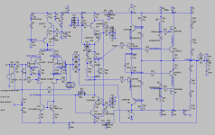
While we wait, cascoded current mirror plus cascoded-cascoded VAS 😎 Amnesis.
Of course, THD near clipping suffers with the extra BJT on the VAS...but Peufeu predicts that TMD will be even lower... 😀
BTW, what power is delivered with a +/-35V swing for an 8 Ohm load?
I am dumb and lazy...
Of course, THD near clipping suffers with the extra BJT on the VAS...but Peufeu predicts that TMD will be even lower... 😀
BTW, what power is delivered with a +/-35V swing for an 8 Ohm load?
I am dumb and lazy...
Attachments

Last edited:
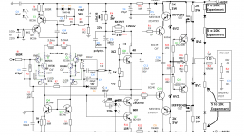
About input section CFP.
Please see the attached schematic.
Lets call R1/R1', R2/R2' and R3/R3' the possible CFP resistors. Usually, only R1/R1' are fited. I chose to use R1=R1'= 1K2 and R2=R2'= 470 Ohm for my last build.
It is adviced to fit pin adaptors (from DIP8 adaptor, for example) and play with the different combinations proposed and evaluate its influence (or the lack of it) on sound.
You can decide to use only R1/R1' or add resistors for the driven BJT but I think either R2/R2' OR R3/R3' should be used, not both simultaneously.
Once the perfect combination is established, it would be wise to use the lowest tempco R available. 😎
Attachments
What IF???
I know you guys are laughing at my RDRD string parallel to the outputs...
Well, this is the second time I connect the strings to an output (the CCS-loaded amp) and, unless I am totally delusional, which may well be the case 😀 , I also noticed a significant change in sound. It was previously a bit "loose" and undefined especially on the highs. Now it is more focused and the images are better defined with more extension to the highs. I'll leave it at that.
That improvement per se is worthy of the expense...
An no, I have not been very scientific meaning I did not went back to listening without the RDRD strings: I had not the courage of desoldering them...
But IF the trick works, what is going on??? 😕
After much (random) though, I came to the following hypothesis: the diode string (the diode) is a passive element in parallel with the active output, right. It does not contribute to the current, voltage, flux, power or musical outputs or whatever nomenclature you prefer. So, IF it is doing something good, it must be as a passive element. The only way I can imagine it having an effect as a passive element is through counter electromotive force or counter-EMF 😉 so when counter-EMF from speaker goes back, it sees two diodes instead of one (per polarity) namely the BJT diode and the humble diode, so it splits (perhaps 50/50) making life easier for the BJT!
If this is so, these are the best 4mA spent ever!...and perhaps I need only an RD and not an RDRD string, which I draw for the sake of symmetry. And also, paralleling multiple RD should make even better effect...at least I hope so. I'll make some RD with clips and we'll see.
Is there a way to model back-EMF in simulation???
I believe there are some complex strategies dealing with this topic, but IF my discovery is true, this trick is much simpler.
Please guys, this is a cheap and fast experiment. Spend $1 and 15 minutes on the mod, no big deal, and tell me that I am crazy. I'll be humble and accept the verdict. 🙁
I need Jimmy Neutron to advice.
To another topic:
I am now on the comparative listening tests between bootstrap loaded VAS and CCS loaded VAS amps. Bear with me...
Last edited:
Dear JOSI1,
Listening tests were interesting. Remember:
The bootstrap version is the musical winner . High praise to Destroyer X
  for the courage to champion and "old" technique. The bootstrap version, IMHO, is more relaxed, more elegant and refined, yet more focused. Even more, the attacks are more violent, the harmonic envelope to the attacks is more coherent and the instrument's texture is more congruent.
Both versions have great energy on the bass/mid-bass, its midrange is on the round and sweet side but the bootstrap has more defined highs which are never aggressive. In fact both MOSFET cascode versions sound HF shy, too diplomatic (tinitus suffering mates will be enchanted) still to my taste. Maybe we are spoiled by years of SS sound...
Anyway, the effect of the cascode element proved to be very significant (contrary to intuition) to the overall presentation, so further experimentation is necessary.
I have yet to find complementary Depletion mode MOSFETs to simulate and try. I strongly suspect that the VFET version will be the most transparent. 😎
The good part is that most units have GDS pinout so it will be easy to swap and test.
I suspect some of the above mentioned differences between the units have influence on the bootstrap being the winner, especially the "charge-transfer" supply (CTS), which is the recommended power supply for the amp.
I have some extra CTS around but I don't know when I could do the transplantation... 😕 The CTS is connected to Balanced Power, which is also recommended.
In summary, the Amnesis with boostraped VAS and MOSFET cascoded BJT output is stable, fully functional, sounds like a 400 Watt animal and is totally the opposite what you would expect from a Blameless amplifier. Better pair it to what you consider detailed and transparent source, transparent interconnects and Berilium tweeter speakers 😀 to reach full potential.
The quest for the perfect output section has not finished though...
I had not the time to experiment with the cascoded current mirror, which is easy to include on the board, and also easy to compare to the 68R emitter degeneration resistors for the current mirror. 😉 I have the file on my other computer but you can see it on my last .asc upload.
Cheers,
M.
Listening tests were interesting. Remember:
The only remaining differences will be:
1) Bootstrap (completed) amp has 2SC5200/2SA1943 main outputs while CCS-loaded (experimental rig) amp has MJ15024/15025 on that position.
2) Bootstrap has silver plated OCC-copper (recommended) wiring everywhere inside while CCS-loaded has sh***ty wires on signal and power supply duties...
3) Bootstrap has "charge-transfer" lineal supply and CCS-loaded has 300W SMPS from connex with 20.000uF extra per rail.
4) CCS-loaded has low quality volume potentiometer at the input, set to maximum.
Cheers,
M.
The bootstrap version is the musical winner
. High praise to Destroyer X for the courage to champion and "old" technique. The bootstrap version, IMHO, is more relaxed, more elegant and refined, yet more focused. Even more, the attacks are more violent, the harmonic envelope to the attacks is more coherent and the instrument's texture is more congruent.Both versions have great energy on the bass/mid-bass, its midrange is on the round and sweet side but the bootstrap has more defined highs which are never aggressive. In fact both MOSFET cascode versions sound HF shy, too diplomatic (tinitus suffering mates will be enchanted) still to my taste. Maybe we are spoiled by years of SS sound...
Anyway, the effect of the cascode element proved to be very significant (contrary to intuition) to the overall presentation, so further experimentation is necessary.
I have yet to find complementary Depletion mode MOSFETs to simulate and try. I strongly suspect that the VFET version will be the most transparent. 😎
The good part is that most units have GDS pinout so it will be easy to swap and test.
I suspect some of the above mentioned differences between the units have influence on the bootstrap being the winner, especially the "charge-transfer" supply (CTS), which is the recommended power supply for the amp.
I have some extra CTS around but I don't know when I could do the transplantation... 😕 The CTS is connected to Balanced Power, which is also recommended.
In summary, the Amnesis with boostraped VAS and MOSFET cascoded BJT output is stable, fully functional, sounds like a 400 Watt animal and is totally the opposite what you would expect from a Blameless amplifier. Better pair it to what you consider detailed and transparent source, transparent interconnects and Berilium tweeter speakers 😀 to reach full potential.
The quest for the perfect output section has not finished though...
I had not the time to experiment with the cascoded current mirror, which is easy to include on the board, and also easy to compare to the 68R emitter degeneration resistors for the current mirror. 😉 I have the file on my other computer but you can see it on my last .asc upload.
Cheers,
M.
Hello maxlorenz,
some days ago you preffered the CCS-VAS temporary
but the final winner is the bootstrapped VAS. Is this still valid when not using a CTS.
Does that mean that a combi layout of both versions has become obsolete.
RDRD String
I gave this option a try and your right there is a change of sound but I would not call it significant. There is more focus but up to now I'm not sure if I like it.
I should use a switch to turn it on/off.
Ecap for bootstrapping
the Ecap always sees a positive voltage between the plus pole and the minus pole namely about U+/2 which is 25V for a +-50V power supply. So there is no need for a 100V Ecap (50V or 63V should be OK).
Thank You for your intensive testing.
Hello maxlorenz,
some days ago you preffered the CCS-VAS temporary
but the final winner is the bootstrapped VAS. Is this still valid when not using a CTS.
Does that mean that a combi layout of both versions has become obsolete.
Ecap for bootstrapping
the Ecap always sees a positive voltage between the plus pole and the minus pole namely about U+/2 which is 25V for a +-50V power supply. So there is no need for a 100V Ecap (50V or 63V should be OK).
Thank You for your intensive testing.
Dear JOSI1,
I was about to post something important but there was an accident nearby and the power went off:
I tried the true cascoded driver with 7V5 zeners on BD139/140 as cascode. It worked and made a significant improvement in transparency, highs and micro-macrodynamics. I no longer miss them compared to before the MOSFETs upgrade. Some "grain" also disappeared. This mod was done on the CCS loaded VAS amp. Of course as the highs are better now there is no longer excessively prominent bass/midbass.
I did not do complete clipping test in the rush to try it on the test system.
I expect this mod to improve also the bootstrapped amp. Now I believe both versions will satisfy. I'll put it this way: the CCS loaded sounds as a "modern amp" and the bootstrapped sounds as an "old school amp", a "70's amp"... 🙂
But then I did something silly: I upgraded also the bootstrapped amp, whose cascodes for the drivers were not properly heat-sinked and I performed power tests that would made DX proud--> It did not clip but I fried the BD139/140s!!! Now I will have to reevaluate if I can put bigger transistors there and properly heat-sinked in case some want to party. Of course, on normal listening levels they should be fine, provided good heat-sinks.
I will use the existing models for bigger BJTs and see if the bias circuit can move them...or maybe I can use also medium power MOSFETs...
some days ago you preffered the CCS-VAS temporary
but the final winner is the bootstrapped VAS. Is this still valid when not using a CTS.
Does that mean that a combi layout of both versions has become obsolete.
For convenience, it would be good to have a combination layout but I understand that it is more difficult.
The CCS VAS can be easily transformed into a bootstrapped, with precise markings about where to do the connections. Bootstrapped has fewer parts, but the difficulty of the bootstrapped lies in the correct biasing.
The other option would be go for the bootstrapped and if anyone wants the CC-VAS he can add a daughter board...
Neither version will disappoint.
I don't know...I'll let you decide because you know better the difficulty of doing a combination board...
RDRD String
I gave this option a try and your right there is a change of sound but I would not call it significant. There is more focus but up to now I'm not sure if I like it.
I should use a switch to turn it on/off.
Crazy, isn't it? 😀
You are right, with so many changes going on one has to permanently re-evaluate previous "upgrades". Previous to the true cascoded drivers it was a good thing but now maybe it will end being excessive... 🙁
Many thanks for your support,
M.
- Home
- Amplifiers
- Solid State
- The AMNESIS amp: a good amplifier, like a gentleman, has no memory.