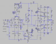
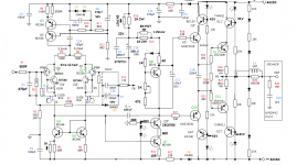
At last, the bootstrapped-LED- cascoded emitter foolower Amnesis. 🙂
Bootstrapping saves a lot of time, trouble and money. 😉
Bootstrapping saves a lot of time, trouble and money. 😉
Attachments
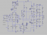

And bootstrapped 44V.
Not bad at all.
It doesn't clip with 1.5V input signal almost +/-40V unclipped output with good THD.
Both 1K resistors that determine the bootstrap take up point must be at least 2W.
I hope you like it.
M.
Not bad at all.
It doesn't clip with 1.5V input signal almost +/-40V unclipped output with good THD.
Both 1K resistors that determine the bootstrap take up point must be at least 2W.
I hope you like it.
M.
Attachments

Last edited:
It is funny to see the Bootstrap cap injecting output signal to the Boostrap node and going over the rail's maximum voltage. 😀
It is centered halfway of the (+) rail. Very clever indeed.
It is centered halfway of the (+) rail. Very clever indeed.
Attachments
Last edited:
I forgot to post Amnesis bootstrapped 44V. It should be totally stable.
I already started the build of the CCS-VAS loaded 44V version (Oops, I already mentioned this; so little time available...) I eventually will compared it to a bootstrapped one.
Guys, don't be lazy, swap you differential pair for a cascoded-CFP and then tell me what you hear.
I already started the build of the CCS-VAS loaded 44V version (Oops, I already mentioned this; so little time available...) I eventually will compared it to a bootstrapped one.
Guys, don't be lazy, swap you differential pair for a cascoded-CFP and then tell me what you hear.
Attachments
Last edited:
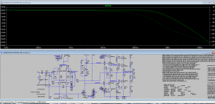
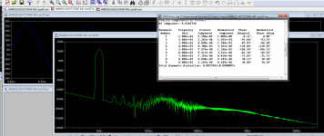
Schematics, with highish bias and measured voltages.
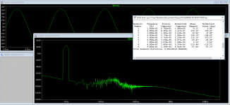
Edit: the emitter and collector resistors for the driver VAS transistor (Q12) have a definite effect on THD. It is advisable to play with them. For example R41 = 1K and R49 330R gives 0.002% THD.
Edit: the emitter and collector resistors for the driver VAS transistor (Q12) have a definite effect on THD. It is advisable to play with them. For example R41 = 1K and R49 330R gives 0.002% THD.
Attachments
Last edited:
Hello maxlorenz,
I follow your excellent work with great interest. Your latest simulation schematics contain some new transistors (2Nxxxx, 2SCRxxxx, 2SCxxxx, 2SAxxxx) and LED LXK2-PW14) compared to your older designs.
Are these devices only used for simulation (existing simulation models)?
In the output stage transistors Q23/Q25 with different cases are used
2N3055 (TO-3) and D45H11 (TO-220).
At least at moderate output levels these transistors have to carry much more power dissipation than 2SC5200/2SA1934.
Dear JOSI1,
Thanks for your kind words.
Yes, I confess I still do not know how to charge new models, so I use whatever I think more or less will do the job.
I don't need much power, but if needed I would parallel output devices.
For the real amp I have here for outputs: 5200/1943 pairs; MJ15024/15025; some big Sanken whose number I don't recall at the moment. For cascodying devices I have: D44/45H11; again the MJ15024/25; some Motorola 2N5885/5883; some VFEts pairs.
For VAS and drivers I have: the ubiquitous BD139/140; MJ15028/31; 2SC4793/2SA1837.
Any advice is welcome.
As for cascodying bias, I tend to prefer LEDs. The voltage for the VAS cascode must be at least 3,2V or around, under the (-) rail. The bias for the drivers must be close to the rails, I would say 2 to 3 volts. I am still experimenting. The bias for the output cascode works well with Hephaïstos 3 diode string.
I dont know if the Hawksworth cascode will work with LEDs; I imagine that it is a no...I have to study further these excellent devices. BTW there are some videos on youtube that claim that LEDs are an alien given technology 😀 If so, thanks a lot.
Cheers,
M.
Hello maxlorenz,
thank you for your quick reply.
If I understood correctly, the output cascode D44H1/D45H11 keeps
the power transistors 2SC5200/2SA1934 under constant voltage condition
some volts above/below the speaker output.
So at least at moderate output voltages D44H1/D45H11 carry most of the power dissipation.
When comparing the data between D44H1/D45H11 and 2SC5200/2SA1934
isn't there a mismatch concerning Icmax and Ptot esp. when using 2 output devices in parallel.
Isn't it possible to use another 2SC5200/2SA1934 insteadt of 44H1/D45H11
for the cascode.
D44H1/D45H11
ICmax=10A
Rth=2.5 C/W
Ptot=50W
2SC5200/2SA1934
ICmax=17A
Rth=0.83 C/W
Ptot=150W
How much sonic improvement did you get by cascoding the output stage
in relation to the other stages.
Indeed, cascodying the outputs makes, IMHO, a big improvement in dynamics, transparency and overall musicality.
I am using D44/D45H11 because they are inexpensive, great transistors and because I don't need much power.
Of course one can choose any BJT combination one desires and the future PCB should have provision for certain elasticity about this, including mayor power T encapsulations.
I'll probably use MJ15024/25 pairs and let the cascode topology take care of the parasitic capacitances...

After many weeks of listening tests, I can say that the "dark", bold character of the sound presentation matches better with "revealing" or bright sounding modern speakers, cables and electronics. No wonder Focal-JMLab chose Lavardin amps.
Listening tests done with all kinds of classical music. Very little jazz.
I suspect the resistors on the input CFP influence the sound, so when the best combination is found, the best quality, lowest tempo resistors must be tried. That is the beauty of the "copper upwards" board. 🙂
Today, the second channel will start its manifestation in the local, physical plane...
I am using 220p Miller cap for now, to be on the safe side.
Last edited:
Oh! Thank you. But this woud take some real estate on the PCB. Good idea though.
One of the Guardian Angels of us, eternal beginers, pointed me to a BIG error on all my simuations: they lack proper load!
Please add an 8 Ohm load to the output if you downloaded the files.
I just dispatched the sunday "parrillada" (BBQ) with good provision of one of our best reds 😀 so, it will take a while before I confront serious labor...
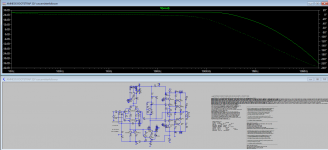
OK. It turned out that the 3 diode string that bias the output cascode limits the output swing to 1/5 of the potential swing that could be available at (+/-)44V supply with my former bias!
We need to go back to basically the same bias as the cascode for the driver (the same as my cascoded VSSA) and we will get more headroom: (+/-)35V swing with (+/-44V) PS.
The good news is that original Hephaîstos cascoded-CFP (with 3 diode string biasing the EF cascode) does not present with early clipping. 🙂
I abandoned previously more complex outputs because they are very hard to get right, but potentially better sounding as my short experience makes me inclined to believe... 😉
Hello maxlorenz,
you emphasized many times how good this amp sounds. You made me really curious about this project. and I decided to do a PCB layout.
I am a little confused about the many variants you tested/simulated. Could you please post a schematic of a variant that is a good starting point for a layout
and contains your findings which are rather mature and show a stable operation. I know there are many things to be varified but I could not wait any longer to listen to this amp.
I will post my layout proposal here hoping for a constructive discussion.
Oh! That would be great.
I was myself aiming at learning how to use those PCB design software but it would take very long. Besides, doing the PCB with "copper up" is the real DIY, IMO, and loaded with fun. 😀
The easiest would be the bootstrapped VAS version (currently playing) but my expectation was to make a PCB versatile enough to test many optional variations, like:
- EF versus simple CE-cascoded VAS.
-bootstrapped versus CCS-loaded VAS.
- conventional CFP for the input (feedback resistor only on the driver collector) versus current version with resistor added to emitters of the driven BJT versus resistors added to collectors of the said driven BJTs.
- differential input "buffered" output, which is a cascode for the cascoded-CFP.
Those variations (and more) are for the Low TMD mods proposed by Hephaïstos and Peufeu.
Next, there should be option for cascoded Drivers.
Finally, options for cascoded outputs. Of course you could try first with conventional EF outputs and then try for yourself IF my claims that cascodying the drivers AND the outputs does (or does not) sound better than the classical option. Anyway, I will procure TO-3 can options for the moment that I try the VFETs cascodying.
I am re-studying the more complex outputs, like Hephaïstos internally cascoded CFP and some variations of double cascoded-CFP.
I will update ASAP the 44V options for your examination, critics and advices: that way the penalty from cascodying does not limit you very much in power headroom.
Attachments
Last edited:
Hello maxlorenz,
you emphasized many times how good this amp sounds. You made me really curious about this project. and I decided to do a PCB layout.
I could be a good sales man. 😀
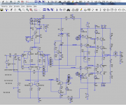
Anyway, a quick adaptation to the bootstrapped VAS version.
There are several topics that are not that critical, like amount of bypass capacitance for certain cascode bias, like current sources ones...etc.
Attachments
Last edited:
Amnesis Amp Layout proposal
Hello maxlorenz and all who are interested,
this is my layout proposal for Amnesis Amp and the related schematic based on your latest schematics. Some variations are already included but it's not easy to do a reasonable layout with all possible variants.
Specifics:
scale 150%
The PCB was designed to be mounted directly on heatsink with a height of 100mm (limits the number of power transistors)
The use of power transistors with TO-3 case is not considered.
The power transistors are mounted on an aluminium block and connected to
the PCB via a screw terminals (at least for the testphase).
Since I don't like a power relay in the speaker path a small signal relay was
added to suppress glitches during power up/down.
A 10 Ohm resistor parallel to choke 2uH in the speaker path is not foreseen on the PCB.
Remarks:
Trimm Pots (5K) in parrallel to both 1k/2W resistors have to be added (if necessary?).
The Ecap 100u/100V for bootstrapping gets up to 15V reverse voltage.
Is a non polarized type necessary?
Comments / proposals are welcome.
View attachment AmnesisAmp-Lay1.pdf
View attachment AmnesisAmp-Schem1.pdf
Good Lord! 😱
I think I underestimated the Task! This is serious stuff.
I hope it does not dissappoint.
Beautiful anyway. Thanks very much for your interest and support.
You will have to give me some time to check...
For now:
1) I see you have a different approach for the feedback resistor.
2) I haven't checked if BC546 as VAS (T16) would tolerate power dissipation. Anyway as it only sees around 5V, maybe another, more ideal part could be found. As driver on the optional EF VAS (T11), I have experimented kaput before, that is why we chose 5550 part.
3) output R//L is easy to fit ouside the PCB, for example on the output cable as I did.
4) See on my last proposal I added resistors on the collectors of your T2 and T5, which are 0 Ohm in that schematics: they are intended as experiments, to interchange between those and R25-R24 (emitters of BC546: CFP) and listen which configuration sounds better. Also, I have experimented with different values, as you can see on the many iterations. For example, in my last built R24=R25= 470 Ohm; R7=R8= 1K2 to 1K5. Listening sessions will tell...
5) The bootstrap capacitor is a good quality electrolytic. I never read about any issues about reverse voltage. Perhaps our more knowleadgeable mates can advise... 🙁 provided offset voltage is OK, I have never experimented problems there. In my personal amp, I paralleled a good quality polystyrene underside...
6) Signal ground is separated to main ground by 10R. I suppose your symbols mean that.
7) I forgot to mention that for my new build (CCS loaded VAS version) I am using 2SC4793/2SA1837 as VAS cascode and drivers, with good effect.
Thanks very much.
Gratefully yours,
M.
About the potentiometers, there are potentially 😀 four:
1) Obviously, there is R18=1K for the Hagerman Vbe multiplier.
2) There is R21 which is used in case that offset is too high. I use it // to R5=68 Ohm, but you use it differently. If you are confident, I'm OK.
3) There are two other optional high value potentiometers which are fitted (in // to R48-R47) in case there is difficulty in setting the right values for the bootstrap node and Vbias node for the drivers, given that in real life there could be different behavior of the VAS (current) and it is even possible that we need a slightly different value for R47-R48, I imagine...
Appart, on my simulations there are excessive power bypass electrolytics: I use one 470uF to 1000uF/50V per rail on the power output section and one 150uF/50V on the input section. That could save some surface.
The Vbias for the cascodes: I am using LEDs these days but resistors or other means can be experimented. For the driver's and output cascodes I am using around 3V (from memory) under the rails, but I will simulate how low can we go: maybe 1.5V to 2V is also feasible. This is to say than even one LED per Vbias circuit can be used. These pass around 4mA only, but I will simulate if more current is needed...
The Vbias for the VAS cascode (which incidentally speaking, I use with a heatsink) needs to left at least 2.5V (that may vary with different BJTs) for the VAS Vce T16, from D. Self, if I remember correctly, for reduced THD.
So the base of T10 should be at least -3.5 under the rail V...I will check.
I use two LEDs in series there, but if one has a 3.5V LED, it should work OK.
More to follow...
M.
Last edited:
- Home
- Amplifiers
- Solid State
- The AMNESIS amp: a good amplifier, like a gentleman, has no memory.