Yeah baby!
What a fun hobby we do have.
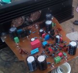
Stereo amp running stable.
Two yellow LED should give you 4V. One white and one yellow should give you +/-4.7V.
I am uploading some videos...poor little speakers.
AMNESIS VFET bootstrapped Darlington bootstrapped output mod. 1. - YouTube
Cheers,
M.
What a fun hobby we do have.
Stereo amp running stable.
Two yellow LED should give you 4V. One white and one yellow should give you +/-4.7V.
I am uploading some videos...poor little speakers.
AMNESIS VFET bootstrapped Darlington bootstrapped output mod. 1. - YouTube
Cheers,
M.
I wonder why you even care to comment...
Anyway, I dedicate to you a very good film:
L'EMMERDEUR 1973 (Lino VENTURA, Jacques BREL) - YouTube
Sincerely yours,
M.
Anyway, I dedicate to you a very good film:
L'EMMERDEUR 1973 (Lino VENTURA, Jacques BREL) - YouTube
Sincerely yours,
M.
Last edited:
Here I hope the dynamics and the attacks can be perceived better.
AMNESIS VFET bootstrapped DARLINGTON Bootstrapped output 3. - YouTube
AMNESIS VFET bootstrapped DARLINGTON Bootstrapped output 3. - YouTube
Guys, this seems a very interesting output to me. IMHO it is far superior to the standard Darlington.
I am still conducting listening tests with different sources and loads.
So far totally stable.
In summary, my VFET version has the goods of the Darlington (stable, immediate and intimate sound, balanced perceived frequency response) and of the QUAD (attacks, great micro and microdynamics, depth of stage, relief, long decays, proper instrument separation, textures...etc) with low parts count. 🙂
I shall retrofit a MOSFET QUAD into a bootstrapped bootstrapped Darlington.
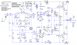
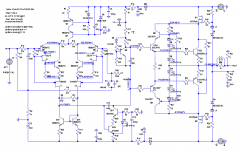
I imagine a 15V Zener would give more headroom. I attach the schema and .asc file. I think it shows good freq response (with 100p Miller) and stability. I welcome any constructive comment.
I know you know this, but anyway I post the response for the cascoded element of the driver part of the Darlington that shows the BJT receives signal both through C and through B. That fact probably helps with dynamics. 😎
I wish you the best and... courage.
M.
I am still conducting listening tests with different sources and loads.
So far totally stable.
In summary, my VFET version has the goods of the Darlington (stable, immediate and intimate sound, balanced perceived frequency response) and of the QUAD (attacks, great micro and microdynamics, depth of stage, relief, long decays, proper instrument separation, textures...etc) with low parts count. 🙂
I shall retrofit a MOSFET QUAD into a bootstrapped bootstrapped Darlington.
I imagine a 15V Zener would give more headroom. I attach the schema and .asc file. I think it shows good freq response (with 100p Miller) and stability. I welcome any constructive comment.
I know you know this, but anyway I post the response for the cascoded element of the driver part of the Darlington that shows the BJT receives signal both through C and through B. That fact probably helps with dynamics. 😎
I wish you the best and... courage.
M.
Attachments
Last edited:
I think these diagrams are clearer.
Notice R49 can be 10R. I believe it is more stable this way. Just in case...
Cheers,
M.
Notice R49 can be 10R. I believe it is more stable this way. Just in case...
Cheers,
M.
Attachments
Last edited:
While I plan to tame the Bootstrapped2 Darlington mod on the QUAD, I did some experiments that I should have done time ago...😱
I disconnected the bootstrap caps (150uF; wholesale buy) for the output MOSFETs and the excess fatness in the midbass is gone and sound became more explicitly delineated and dynamics increased. With the caps on the sound was more "tubey", more romantic. I miss some magic and some depth. I will continue to listen like it is now and then I will try to fit there some good film caps. I compared time ago electrolytics versus film as bootstrap cap, both on VAS and on driver position and I honestly did not hear difference in that short tests...I will try also cap-less bootstrap driver.
I also tried 8V versus 15V zeners for the MOSFET. I think a subtle difference can be heard, 8V making for a recessed, softer presentation and 15V for a more in your face, clearer presentation. So we can more or less tailor our preferred sound...
I post here a simplified version which should work OK and may be easier to build.
Cheers,
M.
Attachments
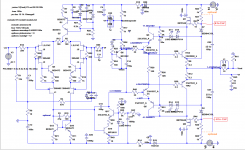
A little mistake filtered through the last diagram: of course, for the bootstrapped boostrapped Darlington, the zener could be from 12V to 15V and for the QUAD from 8V2 to 15V.
The bootstrap output cap dilemma: I put there 1uF Wima MKS4 (MKS1 and 2 could also do it) and no ill effects for the bass nor the transparency were detected. There is a difference with the no-cap state is more in your face, more rough and violent and the 1uF cap state is more refined and delicate.
Am I correcting for the source's faults???
I could live with both versions.
My version of the Elektro-optik link:
AMNESIS VFET plus Elektro-optik link. - YouTube
Cheers,
M.
Attachments
Last edited:
Update:
I removed all the fat from the amp, meaning all bootstrap-caps from driver and output sections are out. I got used to the raw sound of it. I just put there (Vrefs) a ferrite, just in case...I realized that the caps were editing the sound, making a bottle-neck for some of the detail AND dynamics. As my philosophy for the amp is "find a suitable output that can make full use of the input-VAS LTMD sections", one that makes the sound bloom...the sound is now open and detailed from top to bottom, soundstage is bigger and dynamics are scary. If you don't trust me, try it for your selves. 😀 I post the simplified outputs.
Yeah, I was so near...anyway, it is quite interesting that one can tinker with the sound by injecting the positive feedback signal into the bootstrapping active element. One can tailor the output into a more refined and diplomatic sound by installing there a good electro or an ever better film cap.
One of the advantages of the bootstrapped bootstrapped-Darlington is that each BJT of the driver section see a very low VCE, so current can be increased, to certain limits, which seems to improve stability margins a little and probably improves sound, without needing heatsinking. 😎 R48 to 30 to 50R.
With love and respect,
M.
Attachments
Last edited:
Hello Max,
some time ago I removed the bootstrap cap from output to VAS section because I didn`t like the sound at all. The bootstrap caps in the output section are really a matter of taste. I made them pluggable via two IC-contacts so I can easily change/remove the caps while the amp is powered.
I think Ecap C7=220u (feed back network) is also relevant for sound since it is directly in the signal path.
I own some Blackgate caps 47uF/6.3V (N-type non polar) and connected two caps anti-parallel to form a super cap. This is by far the the best solution I found. The sound is very transparent without any coloration.
What Cap did you use in this location.
I`m using the darlington version (bootstrapping output transistor but without bootstrapping driver) since it is very stable and the sound is great.
I updated one testboard to the bootstrapped bootstrapped darlington version.
I did extensive stability tests and discovered no stability problems. Before I update all my 4 amps can you explain
- the reason for adding the 4 ferrites (stability, sound)
- what ferrites did you use and in which way did you add them
Can you describe the advantages ot the bootstrapped bootstrapped darlington final version concerning sound quality.
Best wishes
Dear JOSI1,
Thank you for your valuable inputs.

I will answer in my old style.
Do you mean C33 150uF in the above diagram for the bootstrapped2 Darlington?
I don't understand because the amp wont't work without it.
I am using now good quality Vishay film caps (the green ones) 2*15uF in//. No complaints at all.
I agree, and I remember your clever idea. Do you notice a collapse in soundstage when the caps are in???
I never thought about that cap safe that I use a higher voltage since one malfunctioning amp (high DC) blew one and it took me eons to find the fault back then...
I use there either a 220uF Rubycon ZL or a good quality Vishay electros. I didn't notice change in sound, but I trust you and envy you for being able to use the super-Ecaps. All my non-polar super-Ecaps but one are gone. 🙁
These are great news!
Did you use your dreaded March Track? 😀
I have not modded or retrofitted a QUAD to that version yet because my PCBs are a mess and I hesitate. I am considering building a totally new one.
The following comments pertain to the VFET Darlington version.
The reason to use ferrites was: just in case... 😀 as the amp never oscillated to date, and I tortured it will heavy stuff like Romeo and Juliette Ballet from Prokofiev. Honestly I don't remember the value (most probably 10nH) as I bought them too long ago and lost the record.
I understand you do not consider them necessary, based on your tests...they may be considered optional, then.
Remember to achieve at least 4V for your Vrefs.
In my VFET amp I recognized the attributes of the MOSFET Darlington: immediate and detailed sound but with a want of depth, weight and midbass-bass. When I did the mod it was as if combining the QUAD with the Darlington but without loss in detail, in fact I believe they are more pronounced now, and without blurring of the mid-lows. Now I have my depth and weight back.
The textures improved a lot also, like the textures of the violin, which for me are of utmost importance.
Running a biamped system like I remember you do, should also reveal those improvements, but I recommend you borrow a cheap speaker, even in mono (there are good quality mono recordings) to be able to discern if you like the effect, though I can't imagine you don't liking it... 😀
Or, you can do the bass amps first. 😉
Best wishes of success!
M.
Dancing in the Field of Unlimited Possibilities.
Thank you for your valuable inputs.
I will answer in my old style.
Hello Max,
some time ago I removed the bootstrap cap from output to VAS section because I didn`t like the sound at all.
Do you mean C33 150uF in the above diagram for the bootstrapped2 Darlington?
I don't understand because the amp wont't work without it.
I am using now good quality Vishay film caps (the green ones) 2*15uF in//. No complaints at all.
The bootstrap caps in the output section are really a matter of taste. I made them pluggable via two IC-contacts so I can easily change/remove the caps while the amp is powered.
I agree, and I remember your clever idea. Do you notice a collapse in soundstage when the caps are in???
I think Ecap C7=220u (feed back network) is also relevant for sound since it is directly in the signal path.
I own some Blackgate caps 47uF/6.3V (N-type non polar) and connected two caps anti-parallel to form a super cap. This is by far the the best solution I found. The sound is very transparent without any coloration.
What Cap did you use in this location.
I`m using the darlington version (bootstrapping output transistor but without bootstrapping driver) since it is very stable and the sound is great.
I never thought about that cap safe that I use a higher voltage since one malfunctioning amp (high DC) blew one and it took me eons to find the fault back then...
I use there either a 220uF Rubycon ZL or a good quality Vishay electros. I didn't notice change in sound, but I trust you and envy you for being able to use the super-Ecaps. All my non-polar super-Ecaps but one are gone. 🙁
I updated one testboard to the bootstrapped bootstrapped darlington version.
I did extensive stability tests and discovered no stability problems.
These are great news!
Did you use your dreaded March Track? 😀
I have not modded or retrofitted a QUAD to that version yet because my PCBs are a mess and I hesitate. I am considering building a totally new one.
The following comments pertain to the VFET Darlington version.
Before I update all my 4 amps can you explain
- the reason for adding the 4 ferrites (stability, sound)
- what ferrites did you use and in which way did you add them
Can you describe the advantages of the bootstrapped bootstrapped darlington final version concerning sound quality.
Best wishes
The reason to use ferrites was: just in case... 😀 as the amp never oscillated to date, and I tortured it will heavy stuff like Romeo and Juliette Ballet from Prokofiev. Honestly I don't remember the value (most probably 10nH) as I bought them too long ago and lost the record.
I understand you do not consider them necessary, based on your tests...they may be considered optional, then.
Remember to achieve at least 4V for your Vrefs.
In my VFET amp I recognized the attributes of the MOSFET Darlington: immediate and detailed sound but with a want of depth, weight and midbass-bass. When I did the mod it was as if combining the QUAD with the Darlington but without loss in detail, in fact I believe they are more pronounced now, and without blurring of the mid-lows. Now I have my depth and weight back.
The textures improved a lot also, like the textures of the violin, which for me are of utmost importance.
Running a biamped system like I remember you do, should also reveal those improvements, but I recommend you borrow a cheap speaker, even in mono (there are good quality mono recordings) to be able to discern if you like the effect, though I can't imagine you don't liking it... 😀
Or, you can do the bass amps first. 😉
Best wishes of success!
M.
Dancing in the Field of Unlimited Possibilities.
Last edited:
Hello Max,
thank you for your kind reply.
Let me add some remarks based on my measurements with version
Bootstrapped2-Darlington-final
UPS=+-32V (Lab supply)
UA=14Veff = 40Vss sine
The amp works stable even without C33 (no change to C33=47u) with
resistor loads no load, 8R, 4R.
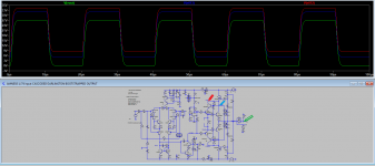
With a quare vave signal UA= +-20V there is no difference in the signal shape
with C33=0 / C33=47u for loads no load, 8R, 4R
When watching the output signal of the amp with a scope you see no difference between C33=0 / C33=47u
However the following differences were observed:
Voltage drop between amp output and R3/R17 (1K) / which is the voltage drop via C33
with C33=47u with C33=0
10Hz 3.3V 5.5V @RL=no load 6.0V @RL=4R
100HZ 450mV 6.0V 6.5V
1kHz 100mV 6.0V 6.5V
5kHz 100mV 6.0V 6.5V
10kHz 100mV 6.0V 6.5V
With C33=47u the voltage swing R3/R17 ->GND is much higher and more independant from the load due to injection of the amp output voltage, The injection will probably reduce the load of the VAS stage.
The lower voltage swing R3/R17 ->GND with C33=0 will be compensated by the overall feedback since there is no difference concerning the output voltage/signal shape.
The next difference is the distortion of the amp.
I made some measurements with the Audio System ARTA and USB soundcard M-AUDIO Transit which has a distortion factor of 0.0006% in loopback mode.
(see doc-File)
With C33=47u the distortion is lower mainly by reduction of K2 which is lower than K3.
With C33=0u the distortion is higher by mainly an increase of K2 which is close to K3.
This might be the reason for a different sound I observed.
I added a switch to activate/deactivate the feedback via C33.
In my audio chain I prefer to listen with C33=0 since with C33=47u the mid range becomes a little too dominant. So an increase of k2 sounds more polite at least to my ears.
(listening test without bootstrapping of driver and no caps in the output section)
Conclusion:
Since the amp works stable with and without feedback via C33 this is another option(at least for me) to taylor the sound.
Best wishes
thank you for your kind reply.
Do you mean C33 150uF in the above diagram for the bootstrapped2 Darlington?
I don't understand because the amp wont't work without it.
I am using now good quality Vishay film caps (the green ones) 2*15uF in//
Let me add some remarks based on my measurements with version
Bootstrapped2-Darlington-final
UPS=+-32V (Lab supply)
UA=14Veff = 40Vss sine
The amp works stable even without C33 (no change to C33=47u) with
resistor loads no load, 8R, 4R.
With a quare vave signal UA= +-20V there is no difference in the signal shape
with C33=0 / C33=47u for loads no load, 8R, 4R
When watching the output signal of the amp with a scope you see no difference between C33=0 / C33=47u
However the following differences were observed:
Voltage drop between amp output and R3/R17 (1K) / which is the voltage drop via C33
with C33=47u with C33=0
10Hz 3.3V 5.5V @RL=no load 6.0V @RL=4R
100HZ 450mV 6.0V 6.5V
1kHz 100mV 6.0V 6.5V
5kHz 100mV 6.0V 6.5V
10kHz 100mV 6.0V 6.5V
With C33=47u the voltage swing R3/R17 ->GND is much higher and more independant from the load due to injection of the amp output voltage, The injection will probably reduce the load of the VAS stage.
The lower voltage swing R3/R17 ->GND with C33=0 will be compensated by the overall feedback since there is no difference concerning the output voltage/signal shape.
The next difference is the distortion of the amp.
I made some measurements with the Audio System ARTA and USB soundcard M-AUDIO Transit which has a distortion factor of 0.0006% in loopback mode.
(see doc-File)
With C33=47u the distortion is lower mainly by reduction of K2 which is lower than K3.
With C33=0u the distortion is higher by mainly an increase of K2 which is close to K3.
This might be the reason for a different sound I observed.
I added a switch to activate/deactivate the feedback via C33.
In my audio chain I prefer to listen with C33=0 since with C33=47u the mid range becomes a little too dominant. So an increase of k2 sounds more polite at least to my ears.
(listening test without bootstrapping of driver and no caps in the output section)
Conclusion:
Since the amp works stable with and without feedback via C33 this is another option(at least for me) to taylor the sound.
Best wishes
Attachments
Dear JOSI1,
Thanks for renewing my interest in those interesting caps!
But I am still confused.
Our "official" schematics show parallel caps, both in main FB-Bootstrap cap (C33) and C7 (220uF) cap. BTW I saw that you did include your super E-cap arrangement there. 🙂
Maybe I wrongly concluded that you attached the feedback directly to the bootstrapped node? That wouldn't be good, would it?
I now realize that you either, left the caps hole (C33) unpopullated, or, maybe used a little cap (//) there?
In the first case, the amp won't be a Bootstrapped VAS amp anymore, but a resistor (2K) loaded common emitter VAS amp, which should have narrower stability margins, at least... 🙁
I remember the bootstrap increases output impedance for the VAS or something alike. Maybe the technical experts can educate us(me) better.
In the second case, the simulations show that the value of the cap does not alter the bass corner frequency, but theoretically it should cover the "frequencies of interest" whose impedance are needed to be increased, so I would say 10uF would be my bet. A Vishay ERO MKT 10uF/63V(?) has 15mm Lead separation, alike the 1uF Wima MKS4, so there you are, in case you want to experiment...
Please clarify.
IF you still find any cap in that position objectionable, then the immediate advice would be to try an active CCS version... 😉
My ALLBJT input amp has only Rubycon ZL 150uF Bootstrap cap so I am experimenting with 1uF Wima MKS4 (red ones) in //, for the following days. First impressions are opposite as those expected. 😱
About the C7 (220uF //0n1 in my case) super E-cap, simulations show a 3Hz lower corner frequency so it is OK, but I would not go lower that value of 94uF. The 220uF cap has a low corner of 1.5Hz, as per simulation.
It is nice to see the actual measurements of the amp being not that bad!
Thanks a lot for that.
Best wishes,
M.
Last edited:
Hi,
Actually, simulations on a better computer show that there is only a slight risk of early asymetric clipping for the non-bootstrapped resistor loaded common emitter VAS, appart of increase of 2nd harmonic. 🙂 (perhaps I tried higher R load as test and that caused lower stability margins)
The +/-44V supply will give us a clean +/-34-35V output, which is more than enough for my requirements.
About the C33 bootstrap cap, the cap-less output QUAD was sounding very open and detailed from top to bottom, as I wrote, but with a little want in bass-midbass weight and depth.
Now I am using 150uF electro (Rubycon ZL) in // with 1uF Wima MKS4: when I added this small capacitance (but big in volume) it was a backward step in the sense of the muddyness of the midrange-midbass coming back; a lack of detail and clear textures. That was not expected.
But, the weight and sense of power of the same range came back, without affecting badly the highs. So instead of desoldering them, I decided to give them the benefit of the doubt...
At the third day things started to improve and now (5th) day I am feelling good about the transparency issue. Now I am confident that it was due to burning-in of the 250V capable caps, which is long, but not so long as the Black Gates. 😀
Note that I have 3 systems always on to compare so it is not a problem of get used to the sound...
I don't recall the Vishay ERO 10uF to be particularly long in bruning-in period.
Next, 270nF Russian Polystyrene caps in // to the above. 😎
Those are even bigger in volume. 😀
Cheers,
M.
Last edited:
Update:
I removed all the fat from the amp, meaning all bootstrap-caps from driver and output sections are out. I got used to the raw sound of it. I just put there (Vrefs) a ferrite, just in case...I realized that the caps were editing the sound, making a bottle-neck for some of the detail AND dynamics. As my philosophy for the amp is "find a suitable output that can make full use of the input-VAS LTMD sections", one that makes the sound bloom...the sound is now open and detailed from top to bottom, soundstage is bigger and dynamics are scary. If you don't trust me, try it for your selves. 😀 I post the simplified outputs.
Yeah, I was so near...anyway, it is quite interesting that one can tinker with the sound by injecting the positive feedback signal into the bootstrapping active element. One can tailor the output into a more refined and diplomatic sound by installing there a good electro or an ever better film cap.
One of the advantages of the bootstrapped bootstrapped-Darlington is that each BJT of the driver section see a very low VCE, so current can be increased, to certain limits, which seems to improve stability margins a little and probably improves sound, without needing heatsinking. 😎 R48 to 30 to 50R.
With love and respect,
M.
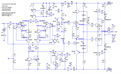
Can you upload an asc sim that can be run, with settings and all.
KT-Cordell models.txt
amnesis.lib
Hi and thanks for your interest in the LTMD amp.
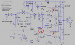
I will upload my latest Amnesis with bootstrapped bootstrapped Darlington MOSFET output project, as I decided not to mod my QUADs that are doing quite well. 😎
I've been playing around with some values so some error might filter-in. Sorry if it is so.
J1-J2 are J103 BL grade P JFETs.
My actual BJT outputs are MJE15024-25.
All the other active devices are OK.
Best wishes.
M.
PS: first attempt did not work as Kordell models exceeds forum capacity to upload. There are sites where you can download it and include it on the folder, as you surely now. The .lib is not accepted file. I will try to change its name and then you change it back to .lib.
PS2:I believe that I included Kordell into amnesis.lib.
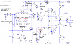
Attachments
Last edited:
Sorry for delayed update: it is parrillada season down here. 😀
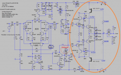
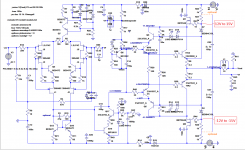
I am a bit rusty. I made several mistakes, like NPN instead of PNP driver 😱, which after correction revealed distorted sound and dimming of the LEDs for the (-) part. I decided to increase Vref from 3.9V to 4.6V through one yellow + one white LED (instead of 2 yellows) but I also detected a cold joint at the output so I am not totally sure what caused the malfunction as I made both repairs at once.
The amp is working totally OK and stable without any further measure.
The voltages are set as follows: MOSFET Gs are set at +/-12.8V (two 6V2 zeners); SC junctions are set at +/-8.9V; BJT bases are set at +/-4.6V.
I am very confident that this amp output will be a winner in terms of stability, sound quality and easiness of construction. 😎
Not the best recording but only to show function:
AMNESIS MOSFET Darlington2 test. - YouTube
The QUADs are sounding very transparent and detailed in a musical way, but on the thin side, depending on sources and material, so I increased the "midrange presence" on the ESS AMT crossover from "Flat" to "Increase" and that made things better.
There is a limit of perception by which, when one increases weight of the midrange- midbass, there is a loss in transparency and detailed texture from that range, apparently...I may be wrong, who knows...
I might revisit the bootstrapped caps for the drivers on the QUAD, to a combination of electro and poliprop/polistyrene caps, which will be bulky but interesting to try.
Best wishes for the equinox,
M.
Last edited:
I finished the second channel with only one mistake. 😀
Sounding good. 😎
In fact, even I am using it with secondary test speakers, I am confident it will satisfy even the most demanding listeners, should they choose to build it. 😀
I ran out of speaker protectors so I am building my own...🙁
My new test speakers:
New test speakers Focal RCX-165. - YouTube
Edit:Yeah, my tablet records like s****, but I am too lazy to buy a decent mic...
Cheers,
M.
Last edited:
Hi Max,
sorry for the late reply.
Darlington 2
In the mean time I changed my 4 amps to the darlinton2.
It works stable even with my critical 'march track'.
The cascoding of the driver improved the sound moderate but
clearly understandable. So this version is my preference and I won't follow up the Quad anymore.
CCS VAS
is no option since it sounds transparent but very thin in the bass and low mid region.
The difference between CCS-VAS and BS-VAS is greater than BS-VAS with and without bootstrapping cap.
I'm still experimenting with the capacity of he BS-Cap.
No signal current of the output transistors
At the moment I set the no signal curernt to 100mA (22mV across the 0R22 resistor)
- What change in sound did you notice when increasing / decreasing the no signal current
- What no signal current do you use, is there a sweet spot.
Output filter L=1-2uH || 10R
The coil is necessary to prevent oscillation with complex mostly capacitive loads.
With L=2uH the inductive resistance of the coil is 0.25 ohms at 20KHz which is negligible to the 10 ohm resistorin parallel. So I didn't use a parallel resistor up to now but now I have doubts if this was a good idea.
For a first listening test I added a good quality 10R resistor 0.5W in parallel since a 5W resistor was not present.
I was surprised that the sound changed more than slightly.
It's not easy to describe but I would say the sound got warmer more pleasant but with a slight loss of detail and transparency.
What is your experience with the output filter (did you ever try without parallel resistor)
What inductivity do you use (I think 1uH is the minimum to prevent oscillation)
What resistor did you use (value, power) and esp. what quality.
I imagine this resistor could be sound relevant although the coil in parallel is dominant in the audio frequency range.
Best wishes
- Home
- Amplifiers
- Solid State
- The AMNESIS amp: a good amplifier, like a gentleman, has no memory.