Hi guys, 🙂 thanks very much for your info.
Dear Itco; yes, dear JOSI1 did his own PCB like that.
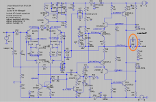
I am trying and re-visiting many techniques to improve stability. One that worked in practice is connecting the Zobel network at the output, that is after the R//L out. Simulation (in my software) shows minor improvement.
After the above, adding a small inductor 😱 to the feedback point also seems to add some improvement.
I tried again alternative compensation (thanks Symon) with no significant improvement...
Reducing the emitter R for the input pair from 100R to 50R adds a little.
Playing with the input filter may also work, depending on the CFP arrangement chosen.
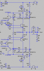
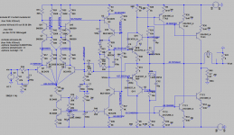
I attach a version with 2SK170 in the input Hybrid CFP.
Dear STV,
Thank you! I will try to decipher how to. 😀
Cheers,
M.
Dear Itco; yes, dear JOSI1 did his own PCB like that.
I am trying and re-visiting many techniques to improve stability. One that worked in practice is connecting the Zobel network at the output, that is after the R//L out. Simulation (in my software) shows minor improvement.
After the above, adding a small inductor 😱 to the feedback point also seems to add some improvement.
I tried again alternative compensation (thanks Symon) with no significant improvement...
Reducing the emitter R for the input pair from 100R to 50R adds a little.
Playing with the input filter may also work, depending on the CFP arrangement chosen.
I attach a version with 2SK170 in the input Hybrid CFP.
Dear STV,
Thank you! I will try to decipher how to. 😀
Cheers,
M.
Attachments
Funny, I never tried the Wilson Mirror option myself. An easy and inexpensive mod to try, though.
The following resistor values also work well on simulation.
Cheers,
M.
The following resistor values also work well on simulation.
Cheers,
M.
Attachments
Updated VFET output (my preference) including SONY 2SK60/2SJ18, which I have 😎 in stock for future units.
Series 54 an higher should produce VGS of +/-12V and higher, depending on last number of series and on bias current, meaning, the higher the series the higher the bias current it can afford.
Cheers,
M.
Series 54 an higher should produce VGS of +/-12V and higher, depending on last number of series and on bias current, meaning, the higher the series the higher the bias current it can afford.
Cheers,
M.
Attachments

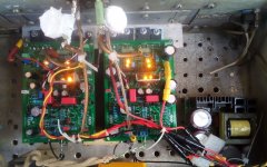
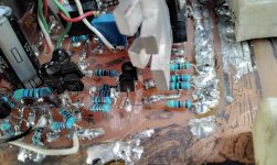
I just posted a picture of my ugly Amnesis QUAD with ALLBJT input project amp in the UGLY thread. 😀
Amazingly, it has not oscillated in many months, maybe a year...😱
UGLY Looking Amp! - but good working
Cheers,
M.
Amazingly, it has not oscillated in many months, maybe a year...😱
UGLY Looking Amp! - but good working
Cheers,
M.
Attachments

Hi Max,
Looking at your amp, gives the impression that you are an aficionado of the chaos theory. 😀 😀
Hans
Looking at your amp, gives the impression that you are an aficionado of the chaos theory. 😀 😀
Hans
Dear Hans,
We have to welcome the bit of Chaos which is inevitable in the change of Ages. As you know, we are leaving Pisces and entering Aquarius (unofficially since Dec 21th 2020) the overlapping being multi-decade, if not longer. 🙂 This is a much anticipated time in the "Platonic Year" or Precessional Cycle.
As I do not resist change and ride over its waves, that helped me a lot to have fun in this epoch and I believe it has also helped my amp with its stability, which in other times would have been considered sub-par, to-say-the-least...😀
Much Love from Chile,
M.
Hi guys, I hope you are all OK.
I have been excercising my KiCad muscles. 😀
Slowly but surely...
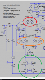
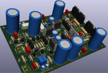
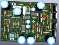
I made some adjustments like placing the output R//L and Zobel on a daughter PCB outside of the main PCB, to reduce the size of it, and adjusted some R values.
I am waiting for price quotes from the maker...I have problems with setting the boundaries of the plate. 🙁
On simulations, playing with the value of the C-feedback from 5pF to 20pF (optional) one can lower the height of the hump around 80megaHz...
Cheers,
M.
I have been excercising my KiCad muscles. 😀
Slowly but surely...
I made some adjustments like placing the output R//L and Zobel on a daughter PCB outside of the main PCB, to reduce the size of it, and adjusted some R values.
I am waiting for price quotes from the maker...I have problems with setting the boundaries of the plate. 🙁
On simulations, playing with the value of the C-feedback from 5pF to 20pF (optional) one can lower the height of the hump around 80megaHz...
Cheers,
M.
Attachments
Last edited:
Hello Mauricio,
Congrats for the finished PCB. My only concern is that the schematic solve the problem with the thermal distortion of the BJTs in the output stage and in the same time the hotest mosfets in the cascode heat them via heatsink. I think it is better to have separate heatsinks for the cascode fets and BJT-s or at least enought space betwen them.
Congrats for the finished PCB. My only concern is that the schematic solve the problem with the thermal distortion of the BJTs in the output stage and in the same time the hotest mosfets in the cascode heat them via heatsink. I think it is better to have separate heatsinks for the cascode fets and BJT-s or at least enought space betwen them.
Thanks Itco. 🙂
I already spotted a mistake on the marking of the parts: an NPN for a PNP. 😱
I am not concerned by the sharing of the HS. IF the low TMD is working also at the Bootstrapped Darlington Output, it should be by influencing the short time variations in T° of the junctions, not the long term T° of the case of the active parts. At least, that is what I understand and hope.
Edit: it is OK to post the Gerber file? Or better, is anybody interested?
Cheers and much Love.
M.
Last edited:
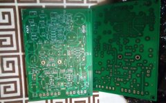
Well, I finally think I detected and corrected ALL (stupid) mistakes...too many (and too stupid) to confess...😀
My troubleshooting technique is lengthy but efficacious.
I already started the corrected version which will be more compact and hence smaller.
I think I soon would be able to offer courtesy PCBs to those who helped and are still interested AND are willing to test with good ears and good equipment 😀😀😀
(My scope kaput)
Cheers and enjoy the wave of pure Divine Unconditional Love arriving.
M.
More fun for me! 😀
After troubleshooting, I tested the simple emitter follower output version up to 120mA current bias and it was stable and sounded rather good.
When I went to the Bootstrapped Darlington Output...you guessed, it started to oscillate like mad! Current jumping from 20mA to 0.5A!
I revised my anti-oscillation strategies until I remembered that I had previously installed a 20pF cap//feed-back resistor (22K*2//) during troubleshooting and once I removed it, stability was obtained. 😱
Now I am testing the stereo amp and it looks kind of stable around 50mA bias current, and it sounds gooood.
I'll have to reduce the area of future boards in order to reduce parasitics...I think 😕
Anyway, first anti-oscillation measure (mandatory) is installing 47nF-100nF from heat-sink to ground as near as possible from the Mosfets, as recommended long ago. I Will include it in future board.
Second anti-oscillation measure, optative (only need-to-do basis) is installing
27R-10nF from base of Cascodying VAS BJT (C4793) to ground.
Then, I can play with some Rs like gate-stopper Rs for the Mosfets, and others...
Anyway, as a first build better go for the emitter-follower output version to make sure everything is OK at the input and VAS sections.
Cheers,
M.
PS: more than 100K views! I missed 99999. Soon 777 replies...
Attachments
Last edited:
Hi guys,
You know how this is...you build one and soon you want to build another project! 😀
I am daily enjoying my Amnesis on his ellegant PCB.
But now I am busy working on a Sansui AU-D5 amp from a friend which continued blowing-up one channel output. I gave up trying to find the fault and repair it and now I am replacing the amp PCB with an amp which I wanted to build for a long time because it has Sziklai ouput 😎 it is the C200 amp from Ampslab, whose inventor I imagine is a member, in its Sziklai version.
I build it and it worked nicelly at first try (if you do not count an accidental solder-short 😀) with a few additions from Rod Elliot's work (to reduce oscillation risk) and from Hagemann's Vbe multiplier.
I am also simulating it with LTMD input (and even VAS) and it should work OK, with some mods. I may use 2SC2240 instead of 2N5551 as input bjt.
If I find it sounds good, I WILL use a simple Sziklai output on my Amnesis, and maybe even a High Voltage version, before even trying my Bootstrapped Sziklai ouput, which seems very delicate to balance...
Have fun,
M.
Attachments
Last edited:
I like the Sziklai output. 🙂
(Though I spent much time getting rid of noise sources from the old Sansui...)
I plan next to adapt Master Hephaïstos' Sziklai output into the Amnesis: AMNESIS HEPHAISTOS. See attachments.
I take the liberty to re-post here some articles by the Master:
index
La distorsion dans l'amplificateur de puissance
La distorsion thermique- tube contre transistor (Héphaïtos)
L'étage de sortie de l'ampli -1- réflexions théoriques (Héphaïtos)
L'étage de sortie de l'amplificateur -2- (Héphaïtos)
http://6bm8.lab.free.fr/Documentations/Revues/Audiophile/1977-1988/34/SORTIE/SORTIE.html
http://6bm8.lab.free.fr/Documentations/Revues/Audiophile/1977-1988/37/SORTIE/SORTIE.html
http://6bm8.lab.free.fr/Documentations/Revues/Audiophile/1977-1988/38/SORTIE/SORTIE.html
For those who can comprehend French, you will see that He spent enormous quantity of linear time exploring, not only Thermal but, many distortions in linear amplification.
Cheers,
M.
Attachments
This output is also interesting, with good film caps.
Attachments
Last edited:
I AM, in the process of upgrading the C200.2 Ampslab. Thanks to Mr Michael Chua, the inventor.
I added a low cost, ALL-BJT, LTMD input section, with units and values I had around. I won't praise again the sonic virtues of that input. Enough to say that this is a cheap, easy to build but very performing amp. The original has double outputs but I do not have enough room inside the Sansui.
The bootstrapped drivers are not yet done.
With matched N5551 inputs offset was at -250mV...just enough to activate the speaker relays. 😀
With matched BC546/556 the offset went down to -30mV. Running at 50mA bias. Very stable. It seems that it would stand a capacitive load, wired as it is now, with only a 1uH inductor at the output.
Cheers,
M.
Attachments
Last edited:
Of course, it is also possible to have a Cascoded-VAS C200.2...
See attachment.
I have posted before the classic article by Hephaïstos:
La distorsion thermique (Héphaïtos)
Inside the "Index" we can find also the following, regarding input stage:
L'étage d'entrée de l'amplificateur -1- : étude théorique (Héphaïtos)
L'étage d'entrée de l'ampli -2- le différentiel classique (Héphaïstos)
L'étage d'entrée de l'ampli -3- différentiels insolites (Héphaïstos)
L'étage d'entrée de l'ampli -4- expérimentations complémentaires (Héphaïstos)
Cheers,
M.
Attachments
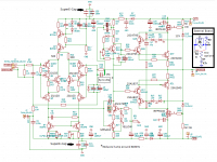
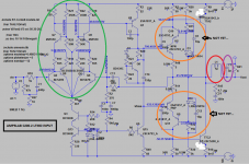
You may have noticed that the LTMD input for the Ampslab C200.2 Sziklai has the bootstrapping element's (2N555X) bases referenced to the emitters of the CFP "drivers", which is the good technical solution, while the Amnesis has the gates of the bootstrapping JFETs referenced to the gates/bases of the drivers...
This decision was taken long ago: basically I stuck with what worked in a time space where I had other bigger problems to face 😀 and since I do not have .Models for the J103 P-channel JFET which I prefer there, not to mention that I always forget to measure the voltages (laziness) inside the CFP input to decide if the emitter reference for the gate would work at all...my fault. 😱
Anyway, since I have some good +/-60V supplies unused, I plan to build a high V version of the Ampslab C200.2, which could be good for rock/parties etc. 😀
The putative LTMD CFP input offered on the modded C200.2 is both easy to build and good sounding, so people can swap it for the stock differential input of their own amps 😀 without excuse and listen for themselves. Use spice or a 500K pot to decide the optimal V reference for the 2N555X (or your option) bases.
Cheers,
M.
PS: I remember there are some diodes to be used there to avoid nasty clipping...hmmm. I edited the .asc file with some diodes...
Attachments
Last edited:
- Home
- Amplifiers
- Solid State
- The AMNESIS amp: a good amplifier, like a gentleman, has no memory.