Hello Hans,
I am using an old TARGET 2001 V8 Design Station. I am not sure if this ancient version generates correct Gerber data.
Furthermore I have no experience with Gerber data and cannot evaluate the results.
For me it is easier and more save to send the Target File to the PCB manufacturer and never had any problems.
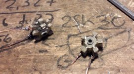
Three hours later, I finally installed the new Honeycomb type DIY VAS resistors. 😎 These are technically better: less C and L. The "pace" of the windings are changing, to reduce them further...
Guys, you don't know what you are missing with this Cascoded VAS that Peufeu invented: long live Peufeu! Wherever he is. 🙂
It sounds astonishly good. The effect is even more pronounced than in the I/V R of my current output DAC. Vastly reduced coloration and increased liquidity, detail and micro/macrodynamics.
This low inductance R is a must, so we must provide option for bigger R, be it DIY or commercial (I will research again; Rhopoint perhaps?) with ampler room for it.
Sorry, I now do not seem to find the site of the PCB builder...I will try harder.
Perhaps I need both a CNC machine and a 3D printer, to build my own PCBs and the DIY resistor formers... 😀
Cheers,
M
PS: I don't wanna go to work...
Attachments
Last edited:
Here is the PCB maker:
https://www.pcbway.es/orderonline.aspx
Apparently they take Gerber. I will ask them if the take Target files.
About the amp, one channel started oscillating again, when challenged with thick speaker cables.
I will follow your finding JOSI1 and install a JFET at the input, as is my TOKIN 2SK180 amp, to make an "internally bootstrapped hybrid Sziklai pair" which is again bootstrapped. 😎 Note that there are several articles that make the hybrid the other way round, with the PNP as driver and the JFET as follower.
Service Unavailable
Perhaps this way it would be even more stable...
Anyway, I will try it and probably recommend it as "standard" version, which makes for a lower parts count and simpler PCB configuration, as you desired.
I will also try to improve the ALLBJT by adding those RC bypasses (all biasing and RC shall be mounted on small daughterboards) that made the square test simulations non objectionable. If that fails, I will use the PNP->JFET configuration this time, as I have more N JFETs than P JFETs... 😀
Perhaps the input circuit is the main culprit of this amplifier with local positive feedback at all its stages... 😱
Apart, I am searching for commercial non-inductive high Q resistors. There also easier ways to wind small R on a cylinder...
Cheers,
M.
Last edited:
When changing a Vas resistor makes such a difference, I think it’s good to try how the sound is without resistor. The best resistor may be no resistor.Three hours later, I finally installed the new Honeycomb type DIY VAS resistors. 😎 These are technically better: less C and L. The "pace" of the windings are changing, to reduce them further...
Guys, you don't know what you are missing with this Cascoded VAS that Peufeu invented: long live Peufeu! Wherever he is. 🙂
It sounds astonishly good. The effect is even more pronounced than in the I/V R of my current output DAC. Vastly reduced coloration and increased liquidity, detail and micro/macrodynamics.
This low inductance R is a must, so we must provide option for bigger R, be it DIY or commercial (I will research again; Rhopoint perhaps?) with ampler room for it.
Sorry, I now do not seem to find the site of the PCB builder...I will try harder.
Perhaps I need both a CNC machine and a 3D printer, to build my own PCBs and the DIY resistor formers... 😀
Cheers,
M
PS: I don't wanna go to work...
Hans
When changing a Vas resistor makes such a difference, I think it’s good to try how the sound is without resistor. The best resistor may be no resistor.
Hans
OK. But the purpose of the resistor is to reach optimal LTMD-constant power, as shown by Peufeu and confirmed by one of our team, but I forgot who he was...maybe you?
Memory Distortion Philosophies - Part 5 : Circuits, continued
Have a nice musical day.
M.
OK. But the purpose of the resistor is to reach optimal LTMD-constant power, as shown by Peufeu and confirmed by one of our team, but I forgot who he was...maybe you?
Memory Distortion Philosophies - Part 5 : Circuits, continued
Have a nice musical day.
M.
Yes, it was me.
But optimal LTMD does not automatically mean that this results in the best sound. That changing a resistor results in an audible difference makes me curious what the effect is with no resistor at all.
It’s a very simple test to perform in the long range of (complex) variations you have already tried.
The best possible sound should be the ultimate goal after all.
Hans
Fair enough. I'll do it some time in the near future as the Springtime is aproaching and my workshop (the patio) gets warmer.
News about the JFET input: done; works OK; sounds great. 😀
Now the input sectioin has 6 P-channel JFEts, which bias themselves automatically. It would be ideal to use the best possible audio JFET (2SJ74?) in the "driver" position (the upper) of the Hybrid Sziklai pair, then a low V JFET as first boostrapped, then a high V capable JFET as second (lowest) bootstrap unit, out of the Sziklai. But then I thought, since the "driver" JFET sees a DS voltage of some hundreds of millivolts, it is working on the linear section of its curve, right, so maybe there will be little effect by swapping different type of units???
It was very hard to make the mod, as the red PCB of the former DX-HR II amp is very crowded. I must confess that I detected a previous (two in fact; one on the driver) mistake on the input section so I cannot "compare" the present JFET input with the previous (which was not correct "internally bootstapped Sziklai") and it is impossible to go back for fear of destruction. Anyway, the sound presentation is very, very open, has low coloration, is very souple as the French say, soft, subtle and elegant. Bass is less prominent as HF is better depicted. You know something is OK when you enjoy what previously was considered boring music. 😀
I also know why that channel oscillated...😱
I noticed it only oscillated when I pulled up or down the lights of the listening room or the soldering station, even if the amp is powered by its own exclusive power system, with its own ground...
From a previous mod, I forgot that I had an RC bypass on the positive side drivers's cascode, base to ground, and that the cap was 100nF! When my final advice was 10 to 22nf, in the hypothetical case of oscillation at peaks. I heard a tump when powering the lights, even when no oscillation ocurred. I changed it to the match the other side's (47nF which is high anyway) and it worked! I will later, reduce it to 10nF, but let me enjoy it first.
I got all necessary (shipping) to make the next VFET Amnesis. I only lack the new PCBs 😀
Love and joy to all.
M.
Last edited:
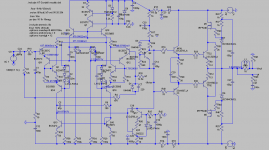
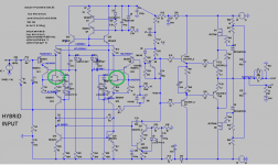
Yet another input option and not too complicated.
Only a pair of P-channels and a pair of N-channels per module for an hybrid Sziklai.
The extra cascoded PNP BJT can be spared. But if you wish to try it, the biasing point can be trimmed with a pot and then the pot replaced by a suitable LED.
I tried this hybrid inverted Sziklai (BJT-->JFET) on one channel and the effect is comparable to the straight one we've done before: darker background; more definition to the images; more detailed and articulated. The ALLBJT though is very "fresh" and alive, if a bit more fuzzy and with a little bit of glare, by comparison...
Attachments
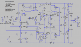
That's not good, no cascodes on current mirror and Vbe multiplier... 😀
We can fix that fault! 😀
This one has better safety margins, I suppose:
Attachments
Well, now the ALLBJT input is no more ALLBJT as it has a 2SK170 as the "follower" of the now hybrid or compound Sziklai pair. The effect is astonishing to say the least. As with the JFET input, the sound is way more focused and the background is darker, as in "concentrated energy", meaning the energy went from the background, which must be silent, to the depiction of the sonic images.
It sounds "colder" than previously, but in contrast, colors and timbres of instruments are truer: timbral accuracy, I use to call it. Instruments placement is also frightening. 😱
I believe this is a great discovery, as it is easier to get N-channels JFETs than P-channels...
I'll post later the schematics.
Cheers,
M.
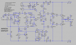
Though it goes against my principles 😀 I publish the AMNESIS SIMPLEST, and other simpler-than-QUAD versions. I did not publish them before because they are obvious...they are not optimized for Miller and input filter but they work, have low THD and seem stable, if one is to believe simulations. 😀
Of course, you can also swap the input "driver" PNP from the Sziklai to a P-channel JFET as JOSI1 (and I) did. Note that this hybrid or compound bootstrapped Sziklai input is also in use in my TOKIN VFET single ended amp, though a "positive" version of it, and it works like a charm.
Of course, you can also swap the input "driver" PNP from the Sziklai to a P-channel JFET as JOSI1 (and I) did. Note that this hybrid or compound bootstrapped Sziklai input is also in use in my TOKIN VFET single ended amp, though a "positive" version of it, and it works like a charm.
Attachments
Last edited:
Hi Max,
can you provide the schematic versions (AllBJT and JFET) with N-JFET 2SK170.
I tested the QUAD version (JFET Input) against the emitter follower (driver not cascoded but output cascoded) and I think I prefer this version because it is less cold and more fluid.
Furthermore this version is stable with my critical test track 'Royal March'. (This track only fails if both driver and output are cascoded).
Do you have a preference for the 1k/3W resistors for VAS-BS and output cascode. Are these resistors sound relevant in a high degree.
Best Regards
Hi Max,
can you provide the schematic versions (AllBJT and JFET) with N-JFET 2SK170.
I tested the QUAD version (JFET Input) against the emitter follower (driver not cascoded but output cascoded) and I think I prefer this version because it is less cold and more fluid. I used to call this version the TRIPLE bootstrapped, now that I think of it...
Furthermore this version is stable with my critical test track 'Royal March'. (This track only fails if both driver and output are cascoded).
Do you have a preference for the 1k/3W resistors for VAS-BS and output cascode. Are these resistors sound relevant in a high degree.
Best Regards
Of course. I did not post it because, though it works very well in real life, the simulation with LSK170A did not work! Edit: it works with LS170C!
I am glad you liked it.
The capacitors // biasing LEDs in the ALLBJT input (C2, C8, C9) are being tested now...I suspect 220n could be too much.
BTW, I forgot to ask how do you like the modded Hagermann Vbe multiplier? Is it stable?
Which one is better EF or Darlington out?
I have all the needed parts to build the VFET bootstrapped output 😎 3 in fact. 😀
I only need PCBs to make it simpler and bullet proof.


With respect to 1k/3W(2W), I have not tried new options yet but my well trained intuition is that non inductive/non capacitive resistors are needed here, I mean at least in the VAS bootstrap. Making DIY resistor that high in value I believe is not a viable option...
Have you guys tried the BRAVE browser??? It's great IMHO.
Best wishes for all humankind.
M.
Attachments
Last edited:
After this great and long work , Maxlorenz , what do you think is memory distorsion in solid state devices ?.
I always thought that it was the effect of temperature in BJT's unions .But Im not sure
Thanks
I always thought that it was the effect of temperature in BJT's unions .But Im not sure
Thanks
Hi Max,
I compared the following output versions (no separate cascode for driver) with JFET input and Hagermann Vbe multiplier.
Darlington: collector of driver transistor connected to source of MOSFET
EF: collector of driver transistor connected directly to power rail
The Darlington version is the clear winner, the sound is more defined but not cold
whereas the EF version sounds a little dull and lifeless.
Both versions are stable with my critical test track 'Royal March'.
A further advantage of Darlington version is that it requires no or only a small heat sink for the drivers.
In a further test with the Quad version I removed the cascoding/bootstrapping of the output transistor with MOSFET (only cascoding driver) but the sound goes in the same direction as with the EF version.
So the cascoding/bootstrapping of the output transistors is highly recommended
while a separate cascoding of the driver may be omitted for stability reasons.
This means that the Darlington version is an excellent compromise between good sound and stability and with it operational safety.
Best Regards
Hi Max,
I compared the following output versions (no separate cascode for driver) with JFET input and Hagermann Vbe multiplier.
Darlington: collector of driver transistor connected to source of MOSFET
EF: collector of driver transistor connected directly to power rail
The Darlington version is the clear winner, the sound is more defined but not cold
whereas the EF version sounds a little dull and lifeless.
Both versions are stable with my critical test track 'Royal March'.
A further advantage of Darlington version is that it requires no or only a small heat sink for the drivers.
In a further test with the Quad version I removed the cascoding/bootstrapping of the output transistor with MOSFET (only cascoding driver) but the sound goes in the same direction as with the EF version.
So the cascoding/bootstrapping of the output transistors is highly recommended
while a separate cascoding of the driver may be omitted for stability reasons.
This means that the Darlington version is an excellent compromise between good sound and stability and with it operational safety.
Best Regards
Dear JOSI1,
Thanks a lot for the clarification. We agree. The Darlington is the best compromise. If anybody has any more tips about how to improve it, you are welcome.
And people still use that boring plain EF output... 😕
The QUAD has this opulent sound that matches well with thinner sounding systems (sources; speakers) but it is risky. Which reminds me about the number of additive ill-products of the multiple local positive FB:
1) I am reading about capacitor induced distortion from articles written by Mr. Bateman, in which he shows increased 2nd harmonic with electros with high biasing (lower than ours) which may be why our bootstrapping with these kind of capacitors have an incremental effect. Now that we can get rid of the active CCS VAS, maybe you can incorporate an option for a film cap, like a 10uF Vishay Roederstein MKT (green) that I have here, which are compact and good, for the bootstrapped VAS.
2) I predict that my future VFET boostrapped output will be not only the best sounding but also the most economic in parts count. For example, a Darlington output bootstrapped with VFETs will not need no biasing circuit at all, only the BJTs, the VFETs and a couple of resistors 😎 That one could be the most transparent of all. 😎
Then I will try to make the cascoded drivers ("Quad") version, which will only need one extra biasing circuit per polarity.
You see, the beauty of your PCB is that it can sustain multiple options. 😀
And one day I will try the Bootstrapped Sziklai output! 😱
Dear Ramcres wrote:
what do you think is memory distorsion in solid state devices ?.
I always thought that it was the effect of temperature in BJT's unions .But Im not sure
Thank you for your interest and for your kind words.
The question is tricky to answer and people more intelligent than myself could answer better. I agree with you that, from conventional wisdom, the modulation of the union's response by instantaneous temperature modification seems the possible most influential cause. I believe we are far more sensitive to time frame variations than to frequency frame variations, when listening to music. So, by limiting to the strict minimum time-variated power (temperature) stress on the critical active parts, we are reaching a more natural time-based response, a more natural "tone envelope" of the ever-changing musical programme. This is sensed as a "concentrated" power which depicts better the impact, curves and decays of notes, with a blacker background. Once you feel it, you cannot go back. I cannot go back.
I already have 4 amps with at least LTMD inputs and one DAC with LTMD output circuit. And the best is still to come.
I will not even try to comment about what is really happening inside the transistors... 😀 I certainly don't think that there are little corpuscles or (little voids) going here or there...
Cheers,
M.
Last edited:
I imagine that by now every DIYaudio member is a fan of "The Electric Universe" theory, visiting its YT channel, "Thunderbolts Project", on a regular basis. 🙂
Here, an update of "The Electric Sun" theory exploration, "The Safire Project":
YouTube
Pure science.
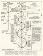
I will also take the liberty to post here a chart from Walter Russel's book "A New Concept of the Universe", which can be read for free at archive.org.
Can mysticism and spirituality be joining science (again) in the near future?
I hope you like both.
M.
Here, an update of "The Electric Sun" theory exploration, "The Safire Project":
YouTube
Pure science.
I will also take the liberty to post here a chart from Walter Russel's book "A New Concept of the Universe", which can be read for free at archive.org.
Can mysticism and spirituality be joining science (again) in the near future?
I hope you like both.
M.
Attachments
Hi Max,I imagine that by now every DIYaudio member is a fan of "The Electric Universe" theory, visiting its YT channel, "Thunderbolts Project", on a regular basis. 🙂
Here, an update of "The Electric Sun" theory exploration, "The Safire Project":
YouTube
Pure science.
I will also take the liberty to post here a chart from Walter Russel's book "A New Concept of the Universe", which can be read for free at archive.org.
Can mysticism and spirituality be joining science (again) in the near future?
I hope you like both.
M.
Everything Oh-Kay with you ?
Im getting a bit worried

Hans

- Home
- Amplifiers
- Solid State
- The AMNESIS amp: a good amplifier, like a gentleman, has no memory.