Hi, John.
No trouble at all. It gives me the impetus to go back
and review my old EE texts. 😀
To answer your last question first, you can definitely
use the Tek. oscilloscope to examine the resulting
ripple. Set it so you can see at least one full period
of the waveform. (120 Hz ripple has a period of
about 8 mS, so set it wider than that.)
The amount of resistance to use would depend on
the amount of capacitance that follows. A little
mathmatical manipulation of the relationship
between the Quality Factor (or "Q") of the filter
and the damping factor of the filter gets you this
handy formula for figuring out the total resistance
you'd need to achieve a certain
"Q":
R >= sqrt (L / C) / Q
Values of "Q" less then 0.707 will not have a peak
at the corner frequency to excite. The excitation of
that peak is what can lead you to ringing, and that
is something you want to avoid.
So to get a Q of 0.5 with your 10 mH choke and
say, 44,000 uF worth of capacitance, your total
resistance should be about 1 ohm.
Figure about a 1 ohm resistor in series with your
choke and the little bit of DC resistance it brings to
the party and you should be fine.
When using the formula for R, I would also assume
every capacitor you have is the smallest possible.
(If they are +/- 20% tolerance, assume they are all
80% of their nominal value.)
Erring on the slightly larger side for resistance will
keep you farther from ringing at the cost of a little
lower voltage at the output and more dissipation in
your power supply filter.
The resistor will be passing your bias current
all the time and therefore dissipating
I(in amps) * I(in amps) * R(in ohms) watts
all the time, so be sure to pick resistors stout
enough to do the job without burning out.
Erik
do you guys have suitable transformers for your Aleph Xs? To me it looks like a custom order.
Peter Daniel said:do you guys have suitable transformers for your Aleph Xs? To me it looks like a custom order.
I ordered mine from Victoria Magnetics, 1kVA (for two channels)with dual primaries, giving me 2x12.5v or 2x25v, along with four pairs of secondaries (one for each voltage rail of each channel). This should work good for my first Aleph-X, then if I decide that I want a more powerful one, I can use it for an Aleph 5. I also ordered it with a faraday shield between the primary and secondary windings.
If others are interested in AX transformers, we can organize a group order from Victoria Magnetics and get a lower price. I talked to him about this, and he will design it to our specifications. Also, once a spec is decided on, then the same spec could be built with different power ratings and still be part of a group order.
Just an idea. I ordered the transformer Friday afternoon, and it should be done sometime next week.
What are others doing for their transformers?
--
Brian
Peter Daniel said:do you guys have suitable transformers for your Aleph Xs? To me it looks like a custom order.
I don't see any reason to get abnormal transformers. I ordered a Hammond transformer from Allied. Dual primaries, dual secondaries, 225VA. I hope I didn't underspecify it...
How is your X going to be arranged, regarding rail voltage and bias current?
Thanks once more, Erik
I've stored the info you posted and will design a ps layout. When the time comes to hook up the scope, perhaps I can trouble you for further instructions. Oh, and one more thing, if I wanted to run an extra lc on the output end of the rlc would I add and extra resistor making it a rlcrlc?
Erik, this has been fantastic and easy to understand information,
John
Why not use thermistors in place of the resistors, which would also fix problems with inrush current? Datasheets on the thermistors are available at:
http://www.thermometrics.com/assets/images/cl.pdf
--
Brian
http://www.thermometrics.com/assets/images/cl.pdf
--
Brian
Hi Brian,
I figured that the chokes would do a pretty good job of limiting inrush current. At 2.25 amps per rail for one pcb, the resistors should be 5 to 10 watters (I think I did that correctly). Does a thermistor deliver that amount of continuous resistance?
John
I figured that the chokes would do a pretty good job of limiting inrush current. At 2.25 amps per rail for one pcb, the resistors should be 5 to 10 watters (I think I did that correctly). Does a thermistor deliver that amount of continuous resistance?
John
jwb,
I bought the same transformer from allied for another project, I found them to be the pissiest looking thing I've ever seen. Do you know how certain product exudes build, quality, and reliability? These don't. I actually arrived with the insulation damaged and ground down varnish of the secondary. I emailed allied for a replacement, never heard back. I had some insulation tape so I fixed it myself.
The 225 VA rating is really barebones for Grey's version.
Brian
I thought about VM for this project as well, how much is your trafo going to cost you?
carpenter,
is there a particular reason for such an unusual choice of filtering topology? 10mH/10 continuous amps is a huge coil, unless you plan to use a northcreek 8 gauge coil, the coil itself is going to have around 1 ohm resistance. If you plan to buy the iron core 10mH/10A from surplussales of nebraska be careful, they spitball the current rating.
Have you tried to simulate the PS? It's a lot of fun. I think your circuit would benefit tremendously from having some capacity before the L.
Sorry, I forgot!...the MAC...Bummer!
Attachments

grataku said:jwb,
I bought the same transformer from allied for another project, I found them to be the pissiest looking thing I've ever seen. Do you know how certain product exudes build, quality, and reliability? These don't. I actually arrived with the insulation damaged and ground down varnish of the secondary. I emailed allied for a replacement, never heard back. I had some insulation tape so I fixed it myself.
The 225 VA rating is really barebones for Grey's version.
It is somewhat craptastic, I admit. The insulation barely clings to the winding and the mounting hardware supplied doesn't fit the torroid. But electrons go in one end and come out the other in an orderly fashion.
I'm certainly willing to hear about better products from Victoria. But I'm afraid practically everyone is building their X with different specs. I want 12V rails and 8A bias.
how do you measure choke resistance?
The 10 amp 10 mH chokes are iron core and when measured with my v/ohm meter read 0.4 ohms, but, the probes read 0.3 ohms when touched to themselves. There is no null adjustment. I subtracted 0.3 from 0.4 and arrived at 0.1 ohms resistance in the choke. Now, with power running through it, the reactance will cause the resistance to increase. Am I correct? I have no way of knowing how much of an increase there may be and I'm not certain how to measure the difference. The idea of the added resistor is to stop any potential ringing in the circuit.
John
10 mH at .1 ohm is a nice piece of coil.
Forget the resistor and enjoy.
(or) put a 10 ohm 5 watt resistor in parallel with the
coil. This will damp out resonance without adding loss.
Forget the resistor and enjoy.
(or) put a 10 ohm 5 watt resistor in parallel with the
coil. This will damp out resonance without adding loss.
Hi Nelson,
That sounds like part of a snubber circuit. Am I correct? I like the idea of avoiding power loss; I'm thinking of using a 16 volt ac dual output (2 x 16v) 500 VA transformer that's just lying around doing nothing. An LC filter will reduce the available voltage to 14.4 volts. I may lose more through the rectifier. Efficiency is a good word here.
John
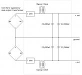
That is the right picture
That picture is what I was describing. Nelson brought up another
interesting way to do it: put the resistor in parallel with the choke.
If you have a simulator, give that a shot. You might want a bigger
resistor than 1 ohm, depending on the results.
If you want to add additional LC sections, I wouldn't necessarily
use the great big chokes after the initial section.
Erik
carpenter said:Is this drawing correctly following Erik's description of a rlc power supply. Can the components in the light gray box repeat themselves for more filtering?
Thanks,
John
That picture is what I was describing. Nelson brought up another
interesting way to do it: put the resistor in parallel with the choke.
If you have a simulator, give that a shot. You might want a bigger
resistor than 1 ohm, depending on the results.
If you want to add additional LC sections, I wouldn't necessarily
use the great big chokes after the initial section.
Erik
Difference
Hi, ca somebody explain me the diffrence between CLCLC and CRCRC.
Whats with mixing them? perhaps CLCRC or CRCLC?
Regards,
Ralf
Hi, ca somebody explain me the diffrence between CLCLC and CRCRC.
Whats with mixing them? perhaps CLCRC or CRCLC?
Regards,
Ralf
Information on constructing a choke input power supply can be found at.
http://www.diyaudio.com/forums/showthread.php?s=&threadid=1898&highlight=gnomus
Hammond makes large chokes at reasonable prices that can be ordered at Mouserelectonics.com. or Angela.com
http://www.hammondmfg.com/5cchk.htm
http://www.angela.com/catalog/transformers/Hammond_Transformers.html
http://www.diyaudio.com/forums/showthread.php?s=&threadid=1898&highlight=gnomus
Hammond makes large chokes at reasonable prices that can be ordered at Mouserelectonics.com. or Angela.com
http://www.hammondmfg.com/5cchk.htm
http://www.angela.com/catalog/transformers/Hammond_Transformers.html
I second the nomination of Hammond power supply chokes.
I've got a 1.5 H choke for my choke-input BoZ. It was about $15
or so when I had bought it from the old Parts Connection.
Erik
I've got a 1.5 H choke for my choke-input BoZ. It was about $15
or so when I had bought it from the old Parts Connection.
Erik
There it is!
Erik, gnomus has the link to the formula I was using. I thought it was in the Aleph 2 thread, but nooooooooooo. It's in the "SOZ choke input filter" thread. Now, imagine that.
You guys have been great; just what the carpenter needed.
John
Erik, gnomus has the link to the formula I was using. I thought it was in the Aleph 2 thread, but nooooooooooo. It's in the "SOZ choke input filter" thread. Now, imagine that.
You guys have been great; just what the carpenter needed.
John
- Home
- Amplifiers
- Pass Labs
- The Aleph-X