I don't understand..
Please elaborate. An oscillator isn't what you want in audio.......
Hey jwb, show a top view of your ps.
Please elaborate. An oscillator isn't what you want in audio.......
Hey jwb, show a top view of your ps.
Re: I don't understand..
The you already understand...
by special request:
carpenter said:Please elaborate. An oscillator isn't what you want in audio
The you already understand...
by special request:
Attachments

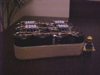
Okay sure. Let's number the capacitors in the picture:
05 06 11 12
03 04 09 10
01 02 07 08
Capacitors 1, 2, 7, and 8 are nearest the rectifier. 1 and 2 are from 14V to ground, and 7 and 8 are from ground to -14V.
1 and 2 are connected to 3 and 4 via 4 0.51Ω 3W resistors. The current is 8A, so these resistors drop 1V, and the second bank (3, 4, 9, and 10) are at +/-13V.
One more round of that gets us to the last bank, where the potential is +/-12V, and the ripple is only 5% whatever it was at the first bank of caps.
Attachments

Thank you very much!
jwb, I've taken a "snapshot" of the screen and will keep the info you've given the rest of us. Do the resistors get hot? Any idea what the final mV amounts to? Also, how many stages can you add (it seems that every stage drops a volt). Could I could take a 20 volt transformer and drop it to 15 volts with 5 CR stages, or is there a point of diminishing return?
John
I think there definitely is a point of diminishing returns. Remember that the Aleph-X circuit will inherently reject ripple anyway, due to it's symmetric nature. So, noise in the circuit caused by power supply ripple will cancel at the speaker outputs anyway. But, of course there can always be asymmetries and so on... Also remember that the Aleph-X will always draw a constant power supply current, regardless of power being delivered to the speakers. There was quite a bit of discussion about this some time ago, and I posted a much more comprehensive set of simulation results and conclusions... it's all back in the thread somwhere. I'm too lazy to go look for it right now, though. 😉
I'm planning to use just a one-stage CRC stage. This already provides superb performance, giving a negligible 13mV ripple on each supply line. This is with 62mF - 0.25ohm - 100mF computer grade (low ESR) caps, result simulated using PSU Designer II. I also tried simulating a CLC using a 2ish mH air-core choke. The results came out only marginally better, at something like 3mV ripple. The trade-off is the potential of forming a resonant LC tank circuit which may cause music-related supply fluctuation at low frequencies. In general though, the Aleph-Xcircuit should be very insensetive to the power supply used.
Another thing to consider is that you lose a lot of power doing this kind of filtering, especially with the X design which draws double the current of a conventional single-output design like the Aleph.
My advice would be to go with a single stage filter, CRC, and no more than a two-stage CRCRC filter. For some people, just a straight C-only supply will work just fine. Reports I've heard indicate that with C-only, a very quiet hum can be heard at the speakers, and CRC makes the amp dead quiet.
LEGO rules
jwb:
I love the LEGO man for scale comparison!
Ah, I'm such a huge LEGO fan, I used to have buckets of that stuff when I was a kid. Come to think of it, I still do... I wouldn't let my parents get rid of it when I moved off to go to university! 😀
jwb:
I love the LEGO man for scale comparison!
Ah, I'm such a huge LEGO fan, I used to have buckets of that stuff when I was a kid. Come to think of it, I still do... I wouldn't let my parents get rid of it when I moved off to go to university! 😀
Thanks
HifiZen, I appreciate your comments; at this late hour even. A CRCRC ps is what I plan to use. I just like to know the boundaries of pragmatism. Shawn's amp has a slight hum and I'm studying ways to avoid this condition. I see no choke or resistors in the ps.
I placed the electrodes of my digital v/ohm meter to the outputs of Shawn's amp. The meter picked up no AC and only a few mV of DC. Is there more that I should be doing in a simple exploration?
John,
The critical inductance figure is only really significant in a circuit where the current draw varies over a large range, and is often cited to select a bleeder resistor to ensure the circuit always draws the minimum current through the choke. A balanced class A design will be fairly constant in current draw.
Please also consider that many of the suggestions made by others re the permissable PSU ripple and noise <i>may not</i> apply to you. IIRC, your horns are about 107dB in efficiency which is probably a minimum of 12dB more than most people and 20dB on average. So things they can't hear may be patently clear on your system. As another horn user, I've had the same issue crop up with such recommendations in the past. Given the same basic noise level in an amplifier, your actual signal to noise ratio will in practice be lower because you are listening at a lower level due to the higher efficiency of your speakers. The minimum filtering I use on all my tube gear, even those stages with shunt regs, is an LC or CLC depending on what parts I have, and many are LCLC. You can easily hear the noise floor drop with the second LC stage, and I don't have to deal with all the hash generated by SS rectifiers (use tube damper diodes).
Cheers
Re: Re: Adjusing Aleph X Help
thanks, Peter
Ralf
Peter Daniel said:
All the info is provided by Grey at the beginning of this thread, so all you have to do is click on the first page.
thanks, Peter
Ralf
Thanks Brett
Right you are about the hf horns and their sensitivity. JBL rates the 2446 compression driver at 110 db. 1w1m; made a believer out of me!
In your LCLC configuration, are you using a snubber network around your chokes? Have you discovered problems with oscillation?
Enjoyed your post,
John
Right you are about the hf horns and their sensitivity. JBL rates the 2446 compression driver at 110 db. 1w1m; made a believer out of me!
In your LCLC configuration, are you using a snubber network around your chokes? Have you discovered problems with oscillation?
Enjoyed your post,
John
Re: Thanks Brett
No oscillation problems either heard or measured as yet
If you haven't built your cases yet, and have space for the chokes, maybe you could add them later.
I'd popped back into this thread after leaving on about p20, because I'm looking at an amp with a lower heat output as my summer amp. Did you end up making PCBs for them?
Cheers
My BMS drivers (400Hz +)measure at nearly 114dB on the hypex horns, and I'm expecting about the same when the new round trax's are done, the midbass are 106dB and even the LABs eq'd flat should be 100+. So I'm really searching for noise to quiet everthing down, even more than it is now. Presently it's got no audible noise or hum, but I find the background the music comes out of is 'blacker' with a lower noise floor, and more enjoyable to me for that.carpenter said:Right you are about the hf horns and their sensitivity. JBL rates the 2446 compression driver at 110 db. 1w1m; made a believer out of me!
No snubber networks are used at the moment, but a recent series of posts on the Joenet have been talking about using an RCR T network bridging the choke with good results. Most of my amps are in the final stages of prototyping and are built onto thin plywood bases. I want to listen and tweak for a while before I do the cases, and I'd planned to look at the T networks after the Christmas holiday period. Out here in the country, I have quite clean mains though, so I might be getting near the assymptote of performance, but if they are audible I'll leave them in.In your LCLC configuration, are you using a snubber network around your chokes? Have you discovered problems with oscillation?
No oscillation problems either heard or measured as yet
If you haven't built your cases yet, and have space for the chokes, maybe you could add them later.
I'd popped back into this thread after leaving on about p20, because I'm looking at an amp with a lower heat output as my summer amp. Did you end up making PCBs for them?
Cheers
Re: another question
If "I" is now in Amps, you have essentially the same
thing. By the way, where did the .88 factor come
from? Does the other thread include a derivation?
When using an LC section, ensure that the
resonance of the circuit is well damped. The
resistance of the choke section is often enough.
If not, add some resistance in series with the choke
as was shown in previous posts.
The neper frequency (which determines the rate
that the amplitude of the voltage falls off with time)
of an RLC circuit is given by the formula
alpha = R / (2*L)
(where R is in ohms and L is in henries)
The resonant radian frequency of the RLC is given
by the familiar
omega = 1 / sqrt (LC)
(L is in henries, C is in farads)
when alpha = omega you have critical damping. That is, the circuit is just on the verge of oscillation.
I prefer to stay in the direction of overdamping,
where (alpha ^2) > (omega^2).
Erik
carpenter said:Seeking critical inductance:
I noted the formula in another thread that the says to me: Henries = V / milliAmps x 0.88.
Can the formula be simplified for solid state circuits (which use chokes in millihenries): mH = V/I x 0.88?
John Inlow
If "I" is now in Amps, you have essentially the same
thing. By the way, where did the .88 factor come
from? Does the other thread include a derivation?
When using an LC section, ensure that the
resonance of the circuit is well damped. The
resistance of the choke section is often enough.
If not, add some resistance in series with the choke
as was shown in previous posts.
The neper frequency (which determines the rate
that the amplitude of the voltage falls off with time)
of an RLC circuit is given by the formula
alpha = R / (2*L)
(where R is in ohms and L is in henries)
The resonant radian frequency of the RLC is given
by the familiar
omega = 1 / sqrt (LC)
(L is in henries, C is in farads)
when alpha = omega you have critical damping. That is, the circuit is just on the verge of oscillation.
I prefer to stay in the direction of overdamping,
where (alpha ^2) > (omega^2).
Erik
a lot to chew on.....
It's an interesting combination you have there, Brett. I have a 150hz tractrix on top being crossed at 350hz. I have a 100hz tractrix midbass (almost can't get it through the doorway). My bass horn is wonderful and loaded with JBL's 2240 18" bass driver. I've been following the LAB project from the beginning. I'm tempted to construct four of them for the right channel. The idea, of course, isn't to get loud, but to have sensitivity so that I can use a beefed up AX designed to handle a very low resistance when all 8 4ohm drivers are running in parallel (can it be done?). I'm very satisfied with the bass from my design. Are you using Eminence's 12" LAB driver (two per horn)? I find the layout is 180 degrees apart from the school of thought I came from. I use light weight coned, highly sensitive, low Q drivers in a 13 foot horn. The LAB is the opposite, i.e. low sensitivity drivers with a very heavy cone, somewhat high Q (much higher than my JBL's at any rate), in a 5 or 6 foot long horn. Still, Tom D. is the engineer and I'm just the amateur explorer. How do your LABs sound with jazz? I tried a high Q driver and it sounded great on rock and roll, but lacked the details required for jazz.
Erik,
Your data is interesting, but way above my head. Can you break it down so that a carpenter can understand? By the way, the critical inductance formula came from the large Aleph 2 thread. I got the impression from jwb that running LCRC caused oscillation. Where do I run the resistors in series and what value would one use?
Many thanks guys,
John
Re: a lot to chew on.....
I'm still building mine (broken drop saw has delayed it a lot), and I have the Eminence drivers ready to go in it. BTW, the lab is 122" from throat to mouth without the flare extenders. I don't see how you'll need 4 a side; with about 6dB of shelving EQ I reckon I'll be close to flat all the way to 20Hz or so and over 100dB sensitivity. I have a little 500W/ch Pro amp to run mine.
Sorry to be short, I'm on the way to work.
Cheers
John,carpenter said:Are you using Eminence's 12" LAB driver (two per horn)? I find the layout is 180 degrees apart from the school of thought I came from. I use light weight coned, highly sensitive, low Q drivers in a 13 foot horn. The LAB is the opposite, i.e. low sensitivity drivers with a very heavy cone, somewhat high Q (much higher than my JBL's at any rate), in a 5 or 6 foot long horn.
I'm still building mine (broken drop saw has delayed it a lot), and I have the Eminence drivers ready to go in it. BTW, the lab is 122" from throat to mouth without the flare extenders. I don't see how you'll need 4 a side; with about 6dB of shelving EQ I reckon I'll be close to flat all the way to 20Hz or so and over 100dB sensitivity. I have a little 500W/ch Pro amp to run mine.
Sorry to be short, I'm on the way to work.
Cheers
Re: a lot to chew on.....
I'll check out the Aleph 2 thread.
Running LCRC doesn't necessarily have to cause
oscillation. It is possible that you may have a certain
frequency which if it gets excited can cause a higher
than expected voltage to pile up. (If you were
you were plotting the voltage of the output of the
filter against frequency, you'd see a little peak at
that frequency, which would be the "omega" I
referenced above. To get it in hertz divide it by
6.283. (2pi)
To help prevent this from happening you should
make sure that you have enough resistance in the
circuit to make the alpha I referenced
(R / 2*L) bigger than the omega value.
Part of your "R" value would be from the choke
itself. It should have a value for "DCR" (DC
resistance) somewhere in the catalog. If it is given
as a "typical" or "average" value, you will probably
want to add some resistors to the circuit, too, in
order to make sure that you always have enough
resistance to dampen the enthusiasm of the
L and C .
You would add actual resistors between the rectifier
bridge and before the choke:
rectifier bridge DC output --- Resistors --- Choke
The capacitor would be at the output of the choke
and going to ground as usual.
Make sure that the resistors can stand up to the
current that you expect to draw:
Power in Watts = (Current in Amps) ^2 * (Resistance in ohms)
If you put a few in parallel with each other, you can
get smaller values of R that can collectively stand up
to the current demands.
Erik
carpenter said:
Erik,
Your data is interesting, but way above my head. Can you break it down so that a carpenter can understand? By the way, the critical inductance formula came from the large Aleph 2 thread. I got the impression from jwb that running LCRC caused oscillation. Where do I run the resistors in series and what value would one use?
Many thanks guys,
John
I'll check out the Aleph 2 thread.
Running LCRC doesn't necessarily have to cause
oscillation. It is possible that you may have a certain
frequency which if it gets excited can cause a higher
than expected voltage to pile up. (If you were
you were plotting the voltage of the output of the
filter against frequency, you'd see a little peak at
that frequency, which would be the "omega" I
referenced above. To get it in hertz divide it by
6.283. (2pi)
To help prevent this from happening you should
make sure that you have enough resistance in the
circuit to make the alpha I referenced
(R / 2*L) bigger than the omega value.
Part of your "R" value would be from the choke
itself. It should have a value for "DCR" (DC
resistance) somewhere in the catalog. If it is given
as a "typical" or "average" value, you will probably
want to add some resistors to the circuit, too, in
order to make sure that you always have enough
resistance to dampen the enthusiasm of the
L and C .
You would add actual resistors between the rectifier
bridge and before the choke:
rectifier bridge DC output --- Resistors --- Choke
The capacitor would be at the output of the choke
and going to ground as usual.
Make sure that the resistors can stand up to the
current that you expect to draw:
Power in Watts = (Current in Amps) ^2 * (Resistance in ohms)
If you put a few in parallel with each other, you can
get smaller values of R that can collectively stand up
to the current demands.
Erik
I run the ps simulations with the program used by hifizen. Although I get about what he gets in terms of ripple voltage,
I don't understand the frequency results. When I zoom in and measure the period of the voltage at the load I get ~8.5us which corresponds to a ~119kHz, close enough to 10 times the ripple frequency. Is this a bug in the program?
I wish the program would spit out datapoints to do an FFT. I simulated out to 100 ms to see if there is a trace of 120 Hz period but the visualization of long periods is kind of useless.
What's up?
Thanks Erik
I appreciate you taking the time to explain the math. Now, just out of curiosity, what ballpark resistor value would one use in the power resistor between the rectifier and choke? I have 4 10amp-10mH chokes, but since they were bought as surplus stock, I have no info on their performance specs. When measured, they appear to have 0.1 ohm resistance.
I can see the value of playing with all aspects of power supply filtering. It's also nice to know what experiments to perform, i.e. lclc, lcrc, crcrc, etc.
I own a used tectronics scope; haven't learned to use it yet. Can it be used to examine the power supply output? How would I make the connections between the scope and the ps?
Again, thanks,
John
- Home
- Amplifiers
- Pass Labs
- The Aleph-X