0.5V across 0.22 ohms as per the original schematic posted by Grey in the 1st post in this thread and also the service manuals for the original Aleph series amps.
AudioFreak
Right, 0.5V in the Aleph service manuals. Sorry for the noise.
Anyhow, it seems time Mr Nelson Pass to say something as they are all 0.66V in the Zen articles.
I close the case. Thanks.
JH
Right, 0.5V in the Aleph service manuals. Sorry for the noise.
Anyhow, it seems time Mr Nelson Pass to say something as they are all 0.66V in the Zen articles.
I close the case. Thanks.
JH
I remember there was this Vbe diskussion allready. If i remember right Mr Pass said something like " this is not rocket science"
jh6you, take a few transistors and measure the Vbe. There will be some tolerace. If you think you need, match left and right channels npn.
jh6you, take a few transistors and measure the Vbe. There will be some tolerace. If you think you need, match left and right channels npn.
this is not rocket science
I guess it might as well be.......
Matching is not required for the BJT transistors. That is why they were chosen since the Vbe is pretty constant between different transistors of the same type for a bipolar transistor. The voltage differences are the result the resistor (R113 for the Aleph 3) connected to the base of the transistor for the purpose of adjusing the bias current in the Mosfet output stage. Go look at the service manual for the Aleph 3 for example. The 0.5 volt across the 0.47 ohm mosfet source resistors is aproximate on the schematic and actually measures considerably smaller than this, as I recall.
http://www.passlabs.com/pdf/aleph/a3srvr0.pdf
She blinded me with science,
Fred
Even lower than 0.5V...?
My general understanding of the barrier potential has been approximately 0.3V for germanium diodes and 0.7V for silicon diodes. I have assumed my projects with the 0.7V. Probably, I need to use updated values in the future...?!?!
I have learned that a good circuit design is insensitivity of the finished circuit to precise values of the components (there are exceptions, tho). What if small approximations create large different results...? Bad circuit design...?!?! Mmm...

JH
My general understanding of the barrier potential has been approximately 0.3V for germanium diodes and 0.7V for silicon diodes. I have assumed my projects with the 0.7V. Probably, I need to use updated values in the future...?!?!
I have learned that a good circuit design is insensitivity of the finished circuit to precise values of the components (there are exceptions, tho). What if small approximations create large different results...? Bad circuit design...?!?! Mmm...
JH
Bad circuit design...?!?!
Taking a deep breath and counting to ten. 1...2...3............
http://www.passlabs.com/pdf/aleph/a3srvr0.pdf
A value of about 0.65 volts for the Vbe is about right for Vbe. Go look at the schematic of the Aleph 3 to see what I am talking about for the following:
The Vbe for Q105 is not the same voltage as what is seen across R120. The presence of R113 supplies a current that causes a voltage drop across R115. The voltage across R120 plus the voltage across R115 will equal the Vbe of Q105. Try a little study of Ohms law and plugging some numbers in for the component values and voltages on the schematic. (ingnoring the 0.5 volts across R120) If this does not become clear after this, I SUGGEST GARDENING AS YOUR NEW HOBBY.
We pursue that which retreats from us,
Fred
Do not shout...I SUGGEST GARDENING AS YOUR NEW HOBBY.

If you do not mind, fu..!, you are right.

I hope Mr Nelson Pass is blind to the above.
Thanks!
JH
update the germanium diodes, but please don't switch to geraniums!
Also please don't eat the daisys. The garden is also a good place for a grounding rod. Thanks for your civilizing influence and subtle humor Karen. I promise not to shout anymore and will limit stiring up the manure to my garden.
As long as the roots are not severed, all is well. And all will be well in the garden,
Fred
Attachments


...my nose facing the ground of the garden...anyway...glad to hear your comeback...forgive me I once called you a heavy drinker...forgive me, Fred, I was once loudly laughing abusing ab...fab...

JH
JH
Hey Nelson,
isn't the show alone worth a timeshare on a new XA200?
Better than the Anna Nicole show!
isn't the show alone worth a timeshare on a new XA200?
Better than the Anna Nicole show!
By the way, Jam has been providing me with a local
concoction known as "bone sucking sauce" for several
years.
No, it's not what you think, nasty boy.
It is to DIY barbecue what Jolt Cola is to programming.
😎
concoction known as "bone sucking sauce" for several
years.
No, it's not what you think, nasty boy.
It is to DIY barbecue what Jolt Cola is to programming.
😎
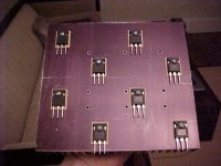
I am all over the digikey, mouser and newark catalogs I can't seem to be able to locate to247 micas or silpads (prefer mica) does anyone know a distributor and the catalog number?
- Home
- Amplifiers
- Pass Labs
- The Aleph-X