Pass DIY Addict
Joined 2000
Paid Member
This one 0.43ºc/w
AAVID THERMALLOY | Semiconductores | Zócalos, Disipadores y Accesorios | Disipadores de calor | Resistencia térmica de hasta 1,3 °C / W |S586/B/250
Please could you post a photo of your amp?
Those sinks look too small also. The "base" of this heat sink is not thick enough to spread the heat evenly across the entire surface. You want the base to be at least 5mm thick, preferably more. You want each fin to stand 60-80mm off of the base plate to provide greater radiating area.
This is a picture of the bottom of my amp.
An externally hosted image should be here but it was not working when we last tested it.
The aluminum base plate of the amp with all of the holes in it measures 10" by 20".
Here is another picture from the top:
An externally hosted image should be here but it was not working when we last tested it.
. Sorry that I don't have any better pictures right now. Both of these are from my web page. Someone in the Mechanical Lab is cutting some custom top and front panels for my amp. When these are completed, I'll post some updated pictures.
Pass DIY Addict
Joined 2000
Paid Member
Do you know the seifert store link?
I was using this link. Look under "high performance" or "special" links in the Extruded category.
I don't think they sell direct- you may need to find one of their distributors. There are other manufactures as well...
Last edited:
Inside my mono amp
And this is the Aleph 3 stereo of my friend Antonio (who wants more power so is looking for J-X)
An externally hosted image should be here but it was not working when we last tested it.
And this is the Aleph 3 stereo of my friend Antonio (who wants more power so is looking for J-X)
An externally hosted image should be here but it was not working when we last tested it.
Hey merlin el mago,
please, follow this link (in EU):
Mali elektronika, Marjan Mali s.p.
Very good stuff!
I'm almost sure that Eric will agree... 😉
 & for fun!
please, follow this link (in EU):
Mali elektronika, Marjan Mali s.p.
Very good stuff!
I'm almost sure that Eric will agree... 😉
& for fun!Hey merlin el mago,
please, follow this link (in EU):
Mali elektronika, Marjan Mali s.p.
Very good stuff!
I'm almost sure that Eric will agree... 😉
Thanks for the link, wich model & how much heatsinks per mono channel?
Pass DIY Addict
Joined 2000
Paid Member
Those look very nice! While I am by no means the last word on heatsinks, I really like HR-245 - a thick plate, lots of long fins, etc. Four of these in 150mm length would provide total cooling capacity of 0.0625c/w for a mono chassis. That would comfortably burn off 400w of power (100w into 8 ohms, 150w into 4 ohms) while keeping your transistors at a safe temperature.
Pass DIY Addict
Joined 2000
Paid Member
Sorry... Eric is the Aleph-x guru... 😉Thanks for the link, wich model & how much heatsinks per mono channel?
Please, look at some of the largest...
& for fun!Those look very nice! While I am by no means the last word on heatsinks, I really like HR-245 - a thick plate, lots of long fins, etc. Four of these in 150mm length would provide total cooling capacity of 0.0625c/w for a mono chassis. That would comfortably burn off 400w of power (100w into 8 ohms, 150w into 4 ohms) while keeping your transistors at a safe temperature.
Lenght is tall, right?
Pass DIY Addict
Joined 2000
Paid Member
Correct! Using the image of the HR-245, the width = 300mm, the height = 83mm, and the length is measured along the top edge of any fin that sticks up from the base (not shown 2-D rendering in the diagram). Length = Tall if you stand it up so it is oriented in the manner that it would be mounted to your chassis.
It would be interesting to see if they can produce a 200mm length of this extrusion and how it would compare in price to the 150mm length.
It would be interesting to see if they can produce a 200mm length of this extrusion and how it would compare in price to the 150mm length.
AFAIK, they can offer any length up to 1,0 m (1000 mm), with or without anodising.It would be interesting to see if they can produce a 200mm length of this extrusion and how it would compare in price to the 150mm length.
Pass DIY Addict
Joined 2000
Paid Member
Sorry... Eric is the Aleph-x guru... 😉
I'm quite flattered, but there are many people around here that know a great deal more than I do. I'm just a copy cat that documents everything...
No, no,... Eric, I saw your "copy work" on your site... it's really great!I'm quite flattered, but there are many people around here that know a great deal more than I do. I'm just a copy cat that documents everything...

Thank you!
& for fun!Absolute DC Offset jumps up as I lower CCS current
This is my first post of diyaudio. I am building an Aleph X and need some help with settling the Absolute DC offset. I have read through most of the post on this subject including the Wiki and the detailed article by Eric without which I wouldn't have had the courage to get started on this amp 🙂
I managed to bring down the absolute DC Offset well below 100 mv using the the V2 pot and it remains reasonably stable, but the voltage across R23/25(390)is 4.95 volts. If I increase V2 towards reducing the current through Q5/Q7, the DC offset goes up to 7 to 8 volts and stays there.
Here are the details:
The Absolute DC Offset is near zero with V2 set such that the voltage across R23 and R25 is about 4.95 volts and I am measuring .63 volts across the .47 ohm source and output resistors. Resulting in 1.34 amps across the 8 IRF 040s that I am using per channel with the rails measuring 14.5 volts.

I would ideally like to run the amp with much lesser current, but If I bring down the voltage across R23 and R25 down to 4.5 volts using V2, the Absolute DC Offset jumps up to 7 to 8 volts and stays there. Changing V1 and V3 doesn't help in bringing down the offset.
I will be using this amp in an active setup to drive the midrange of my Emerald Physics CS 2.3 open baffle speakers. I don’t need too much power as the drivers are 8 ohms and and 96db. I would appreciate any help I can get with this problem.
I recently built an Aleph 3 to drive the tweeters and an F5 for a friend both of which sound Fab!


This is my first post of diyaudio. I am building an Aleph X and need some help with settling the Absolute DC offset. I have read through most of the post on this subject including the Wiki and the detailed article by Eric without which I wouldn't have had the courage to get started on this amp 🙂
I managed to bring down the absolute DC Offset well below 100 mv using the the V2 pot and it remains reasonably stable, but the voltage across R23/25(390)is 4.95 volts. If I increase V2 towards reducing the current through Q5/Q7, the DC offset goes up to 7 to 8 volts and stays there.
Here are the details:
The Absolute DC Offset is near zero with V2 set such that the voltage across R23 and R25 is about 4.95 volts and I am measuring .63 volts across the .47 ohm source and output resistors. Resulting in 1.34 amps across the 8 IRF 040s that I am using per channel with the rails measuring 14.5 volts.
I would ideally like to run the amp with much lesser current, but If I bring down the voltage across R23 and R25 down to 4.5 volts using V2, the Absolute DC Offset jumps up to 7 to 8 volts and stays there. Changing V1 and V3 doesn't help in bringing down the offset.
I will be using this amp in an active setup to drive the midrange of my Emerald Physics CS 2.3 open baffle speakers. I don’t need too much power as the drivers are 8 ohms and and 96db. I would appreciate any help I can get with this problem.
I recently built an Aleph 3 to drive the tweeters and an F5 for a friend both of which sound Fab!
Someone please help
can someone please help me out. I am going nuts waiting for a response. I re-read the first 72 pages of this thread today.
can someone please help me out. I am going nuts waiting for a response. I re-read the first 72 pages of this thread today.
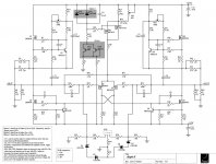
give us exact schematic , or at least link to exact post with schematic
there are more than one floating , so we really don't know which nomenclature you are using
there are more than one floating , so we really don't know which nomenclature you are using
Aleph J-X 50W
I want to know if exist a GB for pcb to make the Aleph J-X 50W, also I need: schematic, psu & transformer (voltage & power) & proper heatsink.
I want to know if exist a GB for pcb to make the Aleph J-X 50W, also I need: schematic, psu & transformer (voltage & power) & proper heatsink.
Zen Mod - Thanks for the reply.
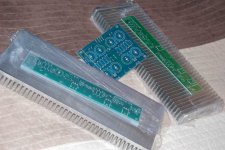
I am using the Aleph-x Rev 1 PCB. Got it from a friend who bought them back in 2003. Here is a pic of the PCB from Eric's website.
http://www.facstaff.bucknell.edu/esantane/movies/pcb-ext.jpg
For the current source I am using a 9.1v zener with the Q6a mosfet (irf9610)
Didn't mention in my original post - I have one channel setup and working. It sounds pretty good.
- Home
- Amplifiers
- Pass Labs
- The Aleph-X