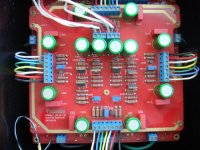
Ths relative offset (one channel) of my AX (Bought from China with photo same as above) is 140mmv when just turn on and steady to 110mv. I guess the mos-fet is not prefect match. (QC in China is no good) Is it due to power mos-fet or 9610, pls help, I'm planning to replace the 9610 with match pair first, is it right.
Pass DIY Addict
Joined 2000
Paid Member
110 mV is not very high, though if you can bring it closer to 0v, its worth doing.
There are a few things to try that can reduce your relative DC offset. The trim pots V1 and V3 each impact relative DC offset. If both sides of the amp are biased equally (compare voltage drop across the source resistors for the output mosfets), then the problem is most likely a result of mismatched 9610s in the input differential. If you don't have the equipment to match them, look for transistors with the same number stamped into the casing, this will indicate that they came from the same wafer when they were manufactured and will potentially be closely matched pairs.
Eric
I'm planning to replace the 9610 with match pair first
Good idea; I think jackinnj has them matched.
look for transistors with the same number stamped into the casing
Sorry, from experience that alone does not help.
Hannes
Pass DIY Addict
Joined 2000
Paid Member
Sorry, from experience that alone does not help.
Hannes
Agreed. Just trying to think of a suggestion in the absence of testing equipment. While all of *my* matched pairs are from the same wafer, you are correct, simply having them from the same wafer is not a guarantee of a match all by itself...
Thanks Eric
I had try adjusted V1, it affect the absolute offset only, the relative offset still 110mv at all time.
I found both side biased equally, Is it wise to adjust the bias of each side to different values so that the relative offset can keep below 50mv
I had try adjusted V1, it affect the absolute offset only, the relative offset still 110mv at all time.
I found both side biased equally, Is it wise to adjust the bias of each side to different values so that the relative offset can keep below 50mv
I find that the adjustment of absolute voltage is depend on bias setting, when turn the abs voltage lower, bias will also lower and vice versa.
While the adjustment of abs voltage have no effect on relative voltage, they are independent to each other.
So it is possible to lower the relative voltage by adjust the bias on both side with different setting. I think within 20% different in bias setting is acceptable.
While the adjustment of abs voltage have no effect on relative voltage, they are independent to each other.
So it is possible to lower the relative voltage by adjust the bias on both side with different setting. I think within 20% different in bias setting is acceptable.
Pass DIY Addict
Joined 2000
Paid Member
I haven't really investigated the effect of biasing each side of the amp at a different setting, but I'm inclined to think this will be most evident as you approach clipping where one side of the amp will clip prior to the other side, thus reducing maximum clean power output. This is only my guess, though.
If you have each side biased equally and still have relative DC offset, my suggestion is to try replacing the differential pair (Q5 & Q7) with a better matched pair.
If you have each side biased equally and still have relative DC offset, my suggestion is to try replacing the differential pair (Q5 & Q7) with a better matched pair.
Yes, different bias on each side will let one side clip before the other and decresase the max output. But if power output is not a make concern( I just use it to drive midrange for muli-amp), this is still a method.
Pass DIY Addict
Joined 2000
Paid Member
If this is all you are interested in, my impression is that you should be fine. If this is incorrect, I'm sure others will jump in... 110mV of offset is not a large compensation to make.
I just replaced the 9610 pairs, offset became 30mv.
There is another question, some hum is heard from speaker at close distance. (can't heard at listening position, but can feel woofer vibrate with finger touching on). One channel is higher than the other.
There are only three grounds ,signal ground L & R & supply ground, they are all connect to a point, the chassis is also connect to signal ground, earth is connect to CL-60 and then to chassis.
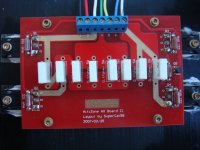
I wonder if the capacitance is not higher enough, not CRC type, only a total of 5600UFx16 or the power mosfets (total of 16) are conncet far away from driver board (with 20cm wires) but with no small capacitors near them.
There is another question, some hum is heard from speaker at close distance. (can't heard at listening position, but can feel woofer vibrate with finger touching on). One channel is higher than the other.
There are only three grounds ,signal ground L & R & supply ground, they are all connect to a point, the chassis is also connect to signal ground, earth is connect to CL-60 and then to chassis.
I wonder if the capacitance is not higher enough, not CRC type, only a total of 5600UFx16 or the power mosfets (total of 16) are conncet far away from driver board (with 20cm wires) but with no small capacitors near them.
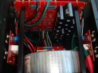
I guess the hum may be coming from the stray field of toroidal, the circuit board is on the top of it within 8cm apart, Is it stray field is max at the top of a toroidal transformer?
Move the board further from the toroid and see what happens. If that works, hopefully you can find a way to make the move permanent. I had that issue with an amp that I tried to stuff too much into too small a case. The good news is I can't hear the hum from my listening position. Now I try to allow more room.
One point on your grounding. I know that you based it on a Pass drawing, but there was an error in that drawing. Your mains ground should connect directly to the chassis. The CL60 should be between the chassis and amps' power grounds.
OK, two points. Try using a small resistance (maybe 50-100R) between the signal ground and your power grounds.
Pass DIY Addict
Joined 2000
Paid Member
30mV sounds like an improvement from 110.
The grounding you describe is different than my own. In my monoblocks, the input signal ground goes only to the ground point on the PCB. The PCB ground goes directly to the power supply ground at the caps. The chassis is directly grounded to AC mains. The thermistor sits between the power supply ground and the AC Mains/Chassis ground.
You might want to try moving the transformer or wiring around a little. If using a toroid, try rotating it a little. Make sure your transformer primary leads are twisted together since they carry AC signal. Do the same for the secondary leads. Try moving the wires around inside the chassis a little. Sometimes small changes can solve the problem you are having.
Two of my three amps are absolutely quiet. The third amp has a transformer with a slight mechanical hum that can be heard through the speaker if you put your ear directly next to the speaker, but cannot be heard a small distance away.
Tuning to your power supply caps, what is your power supply voltage and bias current set to? You have a total of 90,000uF in caps. Do both channels share this 90,000uF so that you have 45,000uF for the positive rail and 45,000uF for the negative rail that feeds both channels? If so, you're looking at about 25,000uF for each rail for each channel which does not sound like enough to me... Please describe your actual PSU configuration for each channel.
Pass DIY Addict
Joined 2000
Paid Member
One more thought about your transformer: Yes, the magnetic field is greatest along the "axis" (both directions pointed to by your mounting bolt) of the transformer. You can try putting a metal plate on top of the transformer and then run your mounting bolt through the plate, through the transformer, then to the chassis. Just make sure that the plate and mounting bolt don't form a completed electrical pathway around the entire transformer do you don't get a shorted turn. Alternatively, mount your PCB on a metal plate (I chose this method - see my construction images on my web page).
5600UF X16 for the whole (L+R) channels, so that's only 5600x4 for each rail for each channel...rail voltage is 22v, there is a total 16 power mosfet (L+R), with 0.25V across source resistor(0.47ohm), bias for each mosfet is 0.54A, total bias(L+R) is 4.2A. The Chinese DIY manufacturer said it has 100wx2 output but it is impossible, the transformer is 660VA..I will post photo later.
I strongly believe the hum come from stray field because one channel is higher than the other but they share the same supply and grounding. I'm planning to cover the transformer with a iron metal can.
I strongly believe the hum come from stray field because one channel is higher than the other but they share the same supply and grounding. I'm planning to cover the transformer with a iron metal can.
Pass DIY Addict
Joined 2000
Paid Member
I have two thoughts for you: 1) the power supply caps may not large enough and 2) try removing the transformer from the chassis and connecting it with longer wires to see if that solves the hum before you go through the trouble of building a metal shield for it. If removing the transformer from the chassis doesn't reduce the hum, then I would look for larger caps.
with a iron metal can
Try to get mumetal or something similar; plain iron is effective for shielding of magnetic fields.
However, please note that mumetal must not be bend as it looses it's properties at the bend and is less effective. Better cut it to pieces.
Hannes
It's a long, long thread, I want to do the 100W version with 2 pcb from Peter Daniel GB but I searched & I can't get the following questions that I need to know:
+-24V will be enough for 100W
Tx 600VA or 400VA
Bias point
Heatsink needed
B.O.M.
All the information required to do the project
Thank you
Felipe
+-24V will be enough for 100W
Tx 600VA or 400VA
Bias point
Heatsink needed
B.O.M.
All the information required to do the project
Thank you
Felipe
Last edited:
1. Yes, 24V is enough to reach 100W
2. See Aleph J-X - diyAudio 600VA or better highly recommended.
3. Search for AXE1-2 developed for the AX but works for AJX
4. See AXE1-2
5. Peter included part values with the boards. Use small form factor resistors for 1/4W parts
6. See the internet, and your library, perhaps a banker, structural engineer, electrician, HVAC contractor, metalsmith, various parts suppliers
Last edited:
- Home
- Amplifiers
- Pass Labs
- The Aleph-X