Good point.
I am happy to fish out some jfets after Xmas (email me) but I suspect the issue lay else where honestly.
I mean I have built a number of these, the Grey Rollins original with 8 IRFP240 (total) using only 15 volt rails was winner..I think would Nelson my review and others.
I will say I was less happy with the higher transconductance 044's and went back to the IRFP240s or 244s
You should be able to hear the difference in the CCs share.
What 220 uf capacitors are you using and let us about the feedback network.
When you get a chance upload some pics.....
You are in NY right.
I have a friend in NY who just finished the Aleph J (with some help) and he is blown away. You might like to check it out.
It just concerns me you have gone to so much trouble and its not happening for you.
Ian
Attachments
Nelson Pass
I appreciate the help. The 150's were Harris. I will double check the 9610's but I believe they were Fairchild. They may have been the IR part and I do recall you mentioning something unfavorable about the IR part. I built this amp over three years ago and I have forgotten many of the details. I used Mills (250 milliohm) on the source resistors and metal film all around. The bootstrap caps were also decent (Yageo), no Blackgates but competent parts.
macka
What was the effect of higher transconductance in your system? What was the impedance profile of the speaker system you used? I thought about changing the stock values in the feedback pair but I was afraid to make the amp unstable. The 044 and 044N have a different transconductance to gate capacitance ratio, which one did you use? I have emailed you for the contact information of your friend.
For what it's worth, I view capacitor quality (not to be confused with capacitance values) as the second most likely factor after MOSFET choice.
Since you say you've heard other peoples' Aleph-Xs and they sounded better, you might want to sit down and make a table of the differences between yours and theirs. Somewhere in that list you will find your problem.
Grey
Since you say you've heard other peoples' Aleph-Xs and they sounded better, you might want to sit down and make a table of the differences between yours and theirs. Somewhere in that list you will find your problem.
Grey
If you haven't checked it with a scope and perhaps a distortion analyzer, then
you are groping in the dark. It could be oscillating, or you could have a poor
connection, or just a crappy part.
😎
you are groping in the dark. It could be oscillating, or you could have a poor
connection, or just a crappy part.
😎
Nelson Pass
I have two oscilloscopes, a Tektronics 442 and an old 2MHz army surplus analogue scope with a full complement of probes. I really don't know which is the better tool. I also have a Fluke 8505A with the AC option cards and the HP 4271 for capacitance measures. You're giving me the sense that there is nothing better than the 9610 for the input pair other than the JFETs already used for this circuit or you would have said so. If this is going to be about tweaking the Aleph-X with the tried and true parts then I should probably be asking for help in the Aleph-X builders thread. I don't want to muck this one up with posts on how I failed to build it right.
I have two oscilloscopes, a Tektronics 442 and an old 2MHz army surplus analogue scope with a full complement of probes. I really don't know which is the better tool. I also have a Fluke 8505A with the AC option cards and the HP 4271 for capacitance measures. You're giving me the sense that there is nothing better than the 9610 for the input pair other than the JFETs already used for this circuit or you would have said so. If this is going to be about tweaking the Aleph-X with the tried and true parts then I should probably be asking for help in the Aleph-X builders thread. I don't want to muck this one up with posts on how I failed to build it right.
I am asking those who have taken on my quest to better my Aleph-X to look in the builders thread for all future posts about measurements, adjustments and tweaks. I will continue to post in this thread only on alternative front end design changes and parts.
To the extent that parts choice, perceived sound quality, front end design (the idea of a JFET front end came up very early in the thread), output bias, behavior under load, etc. are all relevant, it seems to me that it's all quite at home here. It's not as though you're talking about rebuilding an old, broken-down Pioneer receiver or something. The "Build" thread wanders about as much or more than this one does...it's the nature of human beings to think in nonlinear ways.
Grey
Grey
nania said:You're giving me the sense that there is nothing better than the 9610 for the input pair other than the JFETs already used for this circuit or you would have said so.
I didn't mean to imply that. I simply can't think of any offhand.
Ideally you might want something more like a JFET but with
greater transconductance, which is why I mentioned paralleling
JFETs.
Another way to approach this might be to use P ch jfets on the
input driving a 610 as a follower to the Gates of the N ch output
devices. More complex, but it will add gain and bandwidth.
Assuming that the circuit is not oscillating, which you should have
seen with the scope, do you have any distortion measurements?

Over the years, people have threatened to build Aleph variants with any and every part you can think of, either in the front end, the output, or both. How many of these actually came to fruition is anyone's guess. Nelson originally used MOSFETs, but that didn't stop people from proposing bipolars, tubes, and JFETs. Depending on how much you're willing to fiddle with the circuit, all of these can be done, but it's not always easy.
Grey
Grey
Because the x-feedback is a concept I never really 'got' (philosophically yes, electronically no), I wonder whether the feedback in Grey's AX circuit is at some optimal level, i.e. for the optimal distortion cancellation?
If the feedback through R16 and R30 is lessened, will it undermine the X-effect distortion cancellation?
How much could the feedback be reduced and the circuit still work, X-wise?
If the feedback through R16 and R30 is lessened, will it undermine the X-effect distortion cancellation?
How much could the feedback be reduced and the circuit still work, X-wise?
By definition, X is feedback. You can't build a 0dB feedback circuit and have it be X. That said, there's not a lower limit on X feedback...if you want 1dB feedback, it's yours for the taking. The upper limit is whatever the circuit will stand, in terms of open loop gain and stability.
I've got some admittedly rusty braincells that tell me that the open loop gain of a classic Aleph is somewhere around 40dB. Given that the closed loop gain is around 20dB, the math is simple: A standard Aleph has 20dB of negative feedback. By tube standards, that's high, but by solid state standards, it's low. Given that the open loop gain is limited, you're going to have to either redesign the thing for higher gain or accept lower closed loop gain if you want to increase feedback. If you want to decrease feedback, you can, but keep an eye on distortion, DC offset, and closed loop gain--a 40dB gain amplifier is all but unusable in most systems and the performance will decrease.
Grey
Hi everybody
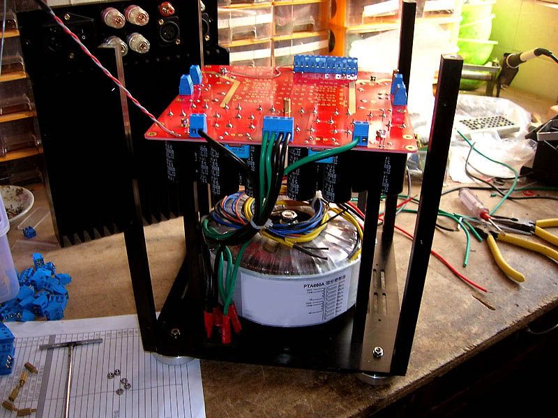
I know this is a old thread but I got hold of 2 18V 300VA trannys and 1 very big heatsink and whant to bild the Aleph X.
Can someone point me to a workable board or to someone that still have some (2) boards for sale.
Thanks
Ric
I know this is a old thread but I got hold of 2 18V 300VA trannys and 1 very big heatsink and whant to bild the Aleph X.
Can someone point me to a workable board or to someone that still have some (2) boards for sale.
Thanks
Ric
Hello Ric
A good idea is to go down to your local electronic shop and purchase some Universal pre-punched experimenters boards, not much to this amp and is very easy to use these boards, plus is more fun!
Dan
A good idea is to go down to your local electronic shop and purchase some Universal pre-punched experimenters boards, not much to this amp and is very easy to use these boards, plus is more fun!
Dan
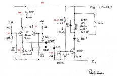
Chois¢â said:Patrick
I tested your balanced protect circuit.
But I got wrong result.
CCS 2mA. Supply voltage 24V.
When relay on state, "+in" and "-in" point were 1.4V both.
To trip relay it needs 5.8V over at "+n" or "-in" point.
Plz help...
you put -Vcc on gnd or on -24V ?
it must be -24V
hi,
i just found this from here http://www.penguinlovers.net/audio/alephx60_proj.html
I did not use RCA, un-balanced mode as it so unstable in DC offset...... Some warns me "NOT" ever use un-balanced mode in A-X....
is this true?
i've been giving up my AX project since it always distorded badly if i increase the volume.
and yes im using unbalance.. i use 10K attenutor as passive volume.
are there any cure to fix this problem.
thanks
audioholik said:.......
are there any cure to fix this problem.
thanks
it's made for both balanced and unbalanced , with balanced as preferable (full SUSY blahblah)
best way , if you want someone to help you , is to bring :
1. exact schematic you use
2.exact measured voltages in important points
3.some pics of gadget itself
or you can wait a little , as soon I sharpen my bean-looking skills problem will be solved 😉
Zen Mod said:
it's made for both balanced and unbalanced , with balanced as preferable (full SUSY blahblah)
best way , if you want someone to help you , is to bring :
1. exact schematic you use
2.exact measured voltages in important points
3.some pics of gadget itself
or you can wait a little , as soon I sharpen my bean-looking skills problem will be solved 😉
right now im using the transformer for something else..
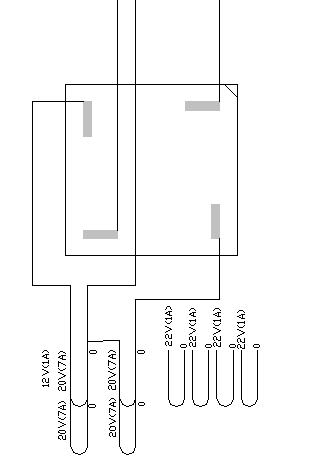
heres the last measurement...
AFAIK it use kristijan schematics of aleph X. with little differences
notice there are lytic caps accros the input.
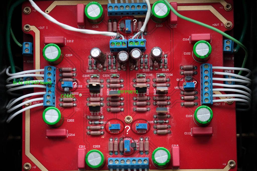

this is ps schematic, is this possible?
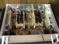
it use 8xIRF240/channel.
quiescent current about 1A. tried lowering to 0.5A but it didnt solve the problem.
thanks for your help

> I tested your balanced protect circuit. But I got wrong result. CCS 2mA. Supply voltage 24V.
> Plz help...
Sorry for ridiculously late reply. I have not been watching the AX threads for years.
CCS 2mA is too low. J508 is 2.4mA, giving a max of 4.8V across one of the 2k resistors. This minus 0.6V drop across the 1N4148, and a further 3.3V across the zener, still gives 0.9V to turn the downstream transistor on. This is not the case with 2mA. You can make up for this by changing the 2k resistors (2x) at the collectors of the BC640s to say 2.4k or even 2.7k. The circuit should then functions properly.
To adjust trip point sensitivity, you can vary the values of both 1k resistors at the BC640 emitters (both simultaneously). E.g. when changing 2k to 2.4k, consider using 1.2k instead of 1k.
You might also need to adjust the value of the 150R power resistor to suit your relay. The valus is given by 2.4V / Relay on current. The 2.4V comes from the 3V zener - BD139 Vbe.
Hope it still helps. I have sent you a PM.
My sincere apologies.
Patrick
- Home
- Amplifiers
- Pass Labs
- The Aleph-X