steenoe said:I doubt that I will ever be good at japanese😉
Counting the fets (source resistors actually) there is 32 in each side of the pic. If the picture in the japanese pdf is in fact a XA100.5, that amounts to a total of 64 mosfets. I could have sworn that Mr. Pass said 40 somewhere?
Steen🙂
I though Mr Pass said 40 too. Perhaps we were both hallucinating? 🙂
Ian.
NP posted that as a comparison to the 24 of the pure single ended version.
He may have only mentioned the total of matching top and bottom numbers, gone up from 6 in parallel to 10.
Papa likes symmetry, so it's hard to read the number of output devices from the output board.
If there's a 1-on-1 relationship, a simpleton would assume 10-10-12 for each side of the mirror.
(a shame Jappon doesn't itch you, they translate Aleph0 to Aleph Buttocks in the XA100.5 paper )
)
He may have only mentioned the total of matching top and bottom numbers, gone up from 6 in parallel to 10.
Papa likes symmetry, so it's hard to read the number of output devices from the output board.
If there's a 1-on-1 relationship, a simpleton would assume 10-10-12 for each side of the mirror.
(a shame Jappon doesn't itch you, they translate Aleph0 to Aleph Buttocks in the XA100.5 paper
)Jacco,
If you are right, then things are going to get very serious for our DIY endeavours if we try to remain totally faithful to the AX100.5. I have to say that I don't understand the need for quite so many devices unless they are something less capable than the IRF240. I need to ponder this 10-10-12 a bit more...
Ian.
A total of 40 doesn't really add up either, i've been thinking about this number thing for weeks.
Suppose the number of output devices in parallel remains 6, a total of 40 then leaves 8 for the single ended bank on either side.
Placing power resistors in parallel has not ever been one of P's attractions, fair to assume that the 64 power resistors are connected to the same number of devices.
The 300 watt power consumption figure speaks against it, however.
I had the same thoughts myself about the 6 and 8 devices. Then again I can't make much more sense of the 10-12 either. I guess the ratio of PP devices to SE CCS devices will depend on the amount of SE bias leaving us back where we started. I wonder if the 300W power consumption tells us anything apart from the obvious total amount of bias?
Ian.
Ian.
This might have been the source of the hallucination😉 The 40 figure is repeated a bit later in GL's thread.
http://www.diyaudio.com/forums/showthread.php?postid=1216044#post1216044
The singleended bias is maybe much smaller than we think?
Seems like there could be 14 fets in each corner with 2 fets for SE biasing each? Take a look at what papa says in the link and a close look at the outputboard.
Steen🙂
http://www.diyaudio.com/forums/showthread.php?postid=1216044#post1216044
The singleended bias is maybe much smaller than we think?
Seems like there could be 14 fets in each corner with 2 fets for SE biasing each? Take a look at what papa says in the link and a close look at the outputboard.
Steen🙂
Attachments
There are too many "if's" in this equation. 40, is that counting SE devices?? 64, is it the 100.5 at all on the pic😕
Lets say (assuming the pic is correct) that 40 is not including the SE devices; that leaves us with 24 of those, 12 for each side. The numbers does compute then, somehow.
Lets say (assuming the pic is correct) that 40 is not including the SE devices; that leaves us with 24 of those, 12 for each side. The numbers does compute then, somehow.
I think (tink) the more you start to look at the practicality and the raw functionality of the design the more obvious the hardware becomes.
At the moment we are still residing over the max SE class operation given some know facts. Non of this is trivial.
At the moment we are still residing over the max SE class operation given some know facts. Non of this is trivial.
There doesn't seem to be a great deal of interest in this project - is it insufficiently radical or too similar to the original Aleph-X perhaps? Is there another reason? I appreciate that I have not yet posted an explanation of how it works but I'd be surprised if that was the problem.
The Alpeh-X thread is 5 years old and very large. I think it is a good idea to start a new thread for the AX.5 or Aleph-X v2.0. As a starting point post #2780 could be used. Maybe then this project gets more interest on the forum.
MEnsing said:
The Alpeh-X thread is 5 years old and very large. I think it is a good idea to start a new thread for the AX.5 or Aleph-X v2.0. As a starting point post #2780 could be used. Maybe then this project gets more interest on the forum.
I did wonder about this too. Anyone else support starting a new thread? Moderators?
Ian.
I think it is a very good idea! Perhaps the best way would be to ask a moderator to split the thread at post:
http://www.diyaudio.com/forums/showthread.php?postid=1235283#post1235283
http://www.diyaudio.com/forums/showthread.php?postid=1235283#post1235283
Hello
I have posted a lot of questions in the Aleph-X builder's thread yesterday. But with no answer.
Perhaps my questions were a bit to much for one post. So I try it again in this forum:
XA100.5 :
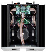
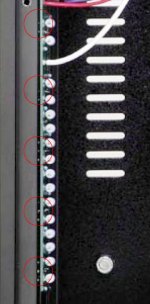
Everybody counts the number of resistors in the Japanese manual not the MOSFETs! When you zoom in the picture you will see the legs of the mosfets. There are 10 devices mounted above and 10 (which you cannot see) below on the heat sink - means 40 devices for the complete amplifier.
I assume eight complementary pairs + four SE-CCS (made of N-ch. devices) per side.
The bias per side must be something about 3A. I would say 2A out of the CCSs and 1A through the P-devices. That gives a dissipation of 13W per CCS.
But my question are the 32 resistors. Each device (CCS and comp.device) needs one source resistor and so there are 12 to much.
What are these power-resistors for? Output to ground - helping to stabilize the DC-offset like the XA-series does?
Greetings
Dirk
I have posted a lot of questions in the Aleph-X builder's thread yesterday. But with no answer.
Perhaps my questions were a bit to much for one post. So I try it again in this forum:
XA100.5 :
Everybody counts the number of resistors in the Japanese manual not the MOSFETs! When you zoom in the picture you will see the legs of the mosfets. There are 10 devices mounted above and 10 (which you cannot see) below on the heat sink - means 40 devices for the complete amplifier.
I assume eight complementary pairs + four SE-CCS (made of N-ch. devices) per side.
The bias per side must be something about 3A. I would say 2A out of the CCSs and 1A through the P-devices. That gives a dissipation of 13W per CCS.
But my question are the 32 resistors. Each device (CCS and comp.device) needs one source resistor and so there are 12 to much.
What are these power-resistors for? Output to ground - helping to stabilize the DC-offset like the XA-series does?
Greetings
Dirk
noisefree said:Hello
I have posted a lot of questions in the Aleph-X builder's thread yesterday. But with no answer.
Perhaps my questions were a bit to much for one post. So I try it again in this forum:
XA100.5 :
Everybody counts the number of resistors in the Japanese manual not the MOSFETs! When you zoom in the picture you will see the legs of the mosfets. There are 10 devices mounted above and 10 (which you cannot see) below on the heat sink - means 40 devices for the complete amplifier.
I assume eight complementary pairs + four SE-CCS (made of N-ch. devices) per side.
The bias per side must be something about 3A. I would say 2A out of the CCSs and 1A through the P-devices. That gives a dissipation of 13W per CCS.
But my question are the 32 resistors. Each device (CCS and comp.device) needs one source resistor and so there are 12 to much.
What are these power-resistors for? Output to ground - helping to stabilize the DC-offset like the XA-series does?
Greetings
Dirk
just jumping in,without really following entire discussion.....
mebbe they're (at least some of them) for modulation of Aleph CCS ,if there is any ......
noisefree said:
XA100.5 :
Everybody counts the number of resistors in the Japanese manual not the MOSFETs! When you zoom in the picture you will see the legs of the mosfets. There are 10 devices mounted above and 10 (which you cannot see) below on the heat sink - means 40 devices for the complete amplifier.
I assume eight complementary pairs + four SE-CCS (made of N-ch. devices) per side.
The bias per side must be something about 3A. I would say 2A out of the CCSs and 1A through the P-devices. That gives a dissipation of 13W per CCS.
But my question are the 32 resistors. Each device (CCS and comp.device) needs one source resistor and so there are 12 to much.
What are these power-resistors for? Output to ground - helping to stabilize the DC-offset like the XA-series does?
Greetings
Dirk
You must have better eyesight than I do. I can't see the MOSFET legs but the resistors are much easier to count. Are you sure that there no other devices lurking where you can't see them? I'm also not sure about the 8 complimentary and 4 SE-CCS. The classic Aleph0 used 8 SE-CCS for 2A bias and this was not a symmetrical design, i.e. would translate to 16 devices for this design. I still don't understand why so many are required unless it is simply a rugedness issue.
How did you arrive at the 2A for CCS and 1A for P-devices? Would this allow 100W into 8 ohms? I agree that 3A overall per side is consistent with the 300W rating for power from the wall. 3A SE is clearly not enough but your 2A + 1A may be on the grounds that PP is more efficient (output = 2 x bias current).
So what are the 'other' resistors for? I guess it depends on whether there really are 40 or 64 output devices. If you are convinced that there are just 40 then we have another conundrum. I don't think the DC-offset needs stablising in this design and even if it did, 12 resistors would seem to be overkill.
I'm quite sure there is no CCS modulation in the XA100.5 (to answer "Zen Mod").
Ian.

Hi ZEN MOD, hi Ian,
yes, I'm quite shure that there are 20 mosfets. You will only see that in the XA100.5 manual not in the 60.5 or 30.5. There you will see the legs a bit shining between board and heat sink. The distance between the fets are always the same.
I don't know if my assumption with 4 CCS per side is correct.
You are right Ian that the Aleph0 uses 8 devices for 2A SE-current, but they have a bit less than double the supply-voltage to handel - each CCS-device 10W (idle).
With 2A SE-current and 1A PP-current through the P-ch. your maximum reachable mixed SE-PP-classA peakcurrent will be 4A (2A + 2x 1A) which will give you 64W RMS at 8Ohm.
When you wanna reach 100W RMS at 8Ohm in classA (SE-PP-mix) the SE-CCS must set to 1A and the p-ch.-bank 2A.
I know there is no hint for such calculations and all is speculation!
It makes the most sense for me that the SE-current is as high as possible, but leaving enough current left over for the p-ch. bank (in my calculation 125mA/device). So I'm coming to the conclusion that the SE-current is maximum 2A = 50W dissipation, a bit too much for 2 devices and too less for 6.
And yes I'm quite sure too that there is no CCS modulation.
Another hint:javascript:smilie(' ')
')
smash
It seems that the XA100.5 uses seperate windings for the front end, XA60.5 and XA30.5 don't...
Dirk
yes, I'm quite shure that there are 20 mosfets. You will only see that in the XA100.5 manual not in the 60.5 or 30.5. There you will see the legs a bit shining between board and heat sink. The distance between the fets are always the same.
I don't know if my assumption with 4 CCS per side is correct.
You are right Ian that the Aleph0 uses 8 devices for 2A SE-current, but they have a bit less than double the supply-voltage to handel - each CCS-device 10W (idle).
With 2A SE-current and 1A PP-current through the P-ch. your maximum reachable mixed SE-PP-classA peakcurrent will be 4A (2A + 2x 1A) which will give you 64W RMS at 8Ohm.
When you wanna reach 100W RMS at 8Ohm in classA (SE-PP-mix) the SE-CCS must set to 1A and the p-ch.-bank 2A.
I know there is no hint for such calculations and all is speculation!
It makes the most sense for me that the SE-current is as high as possible, but leaving enough current left over for the p-ch. bank (in my calculation 125mA/device). So I'm coming to the conclusion that the SE-current is maximum 2A = 50W dissipation, a bit too much for 2 devices and too less for 6.
And yes I'm quite sure too that there is no CCS modulation.
Another hint:javascript:smilie('
')smash
It seems that the XA100.5 uses seperate windings for the front end, XA60.5 and XA30.5 don't...
Dirk
Frankly I dont think its the right approach to be cloning the design based on visual observations.
No dount there are choice just as there were in the A Aleph.
Earlier in the week in investigated the bias requirements and came up with this.(I accept no responsibility for accuracy or error)
Assuming a power dissipation constraint of 300 watts I decided to attempt calculation of the maximum SE bias.
Given the Aleph 0 type CS I looked at the JLH article and used it as a basis for the calculations
:
The peak-voltage swing and mean output current
can be calculated quite simply from the well-known relationships W=I2.R and V=I.R, where the symbols
have their customary significance. (It should be remembered, however, that the calculation of output
power is based on r.m.s. values of current and voltage, and that these must be multiplied by 1.414 to
obtain the peak values, and that the voltage swing measured is the peak-to-peak voltage, which is twice
the peak value.)
In a 100 watt AX.5 design 300 watts is the dissipation model and the same current will fow through both sides so we divide 300/2 = 150 watts maximum power dissipation per side.
For a target output of 32 watts rms into 8 ohms , 16 Volts rms or 45.3 VP-P
The bias current required is 2 x 1.414 = 2.8 amps (I AP- P)
There is no active CS so there is no current share. The active half must therefore deliver the full bias to remain in class A
Therefore, for 100 watts in 8 ohms A/B for a normal X amp the requirement is a supply rail of about +- 25 volts (minimum for best function of power fets) so the power dissipation in SE bias territory with this supply voltage is 2.8 x 2 x 25 x 2 = 280 watts.
PP class A bias
From Borberly's formula for PP class A bias 50/100 watt article
I Bias = 1/2 VC/R load where VC =34.64 and R=8
Equals = 2.165 A
The output stage will deliver a peak current of 2 x I Bias =4.33 amps before leaving class A, which is the equivalent of 3.06 amps RMS.
The class A output power into 8 ohms is
Po =Vrms x Irms = 24.49 x 3.06 = 75W.
**********************************************
For 100 watts into 8 ohms the rms voltage is about 28.3 V RMS, or 39.6 Volt peak.
Applying the above formulae = 2.5 A, so the output stage will deliver a peak current of 2 X I bias = 4.95 amps (peak) before leaving class A . Again looking at the above formulae this the equivalent of 3.5 amps rms where Vrms x Irms = 28.3 x 3.5 = 100 W
So in this instance of PP class A the bias is 2.5 amps, thus with the AX.5 amp design assuming min 25 volt rails that is 254 watts dissipation per channel in the PP class A Zone.
The actual design figure may need some adjustment due to voltage drops across the active devices and other losses.
The results for driving 4 ohms will also need calculation at some point.
The point is of course tue class A can only exist while there is sufficient bias.
So from here its a case of working out the desire dissipation per device and allowing adequate margin to avoid failure in the case of a shorted output stage as I discussed with Ian.
My view is when the pull circuit is used the design will not current limit like the Aleph and the lower the load impediance the harder it will pull beyond class A. A short will not instantly create any heat as such but could blow a device and cause serious damage to your expensive loudspeaker.
The number of devices is therefore not a direct indicator of power sharing necessarily
Macka
Guys, at the risk of repeating myself, I don't think it's worth obsessing over the details of the circuit Nelson's using. How many angels can dance on the head of a pin? Couldn't care less. Ditto for MOSFETs. How many are in the production XA .5? Couldn't care less. It's the topology you're after and there's more than enough to be getting on with already. At the rate you're going, nothing will ever get built because the design is caught up in committee and the committee is fretting over how many screws are in the chassis.
I posted the original Aleph-X schematic and people actually built the silly thing without getting weirded out over details. You know what? It worked. As a consequence, people have had music for the last five years. I guess I'm fortunate people didn't flip out over details back then.
Ian has posted a wonderful schematic. I suggest you quit second-guessing the man and start prototyping.
Whew, I'm starting to be glad I didn't undertake the 2.0...
Grey
P.S.: I'm perfectly happy to have the 2.0 in this thread. At the moment I don't think the 'lack of attention' is due to where the discussion is taking place. I think it's that people are taking a wait and see attitude.
Grey,
I agree. We decided earlier that we would shoot for a 100W version but nobody said it had to be exactly the same as the AX100.5. No doubt some folks will wish to build it with more or less power too. Since we don't know how much SE bias to use (although we know it cannot be more than 1A to give 100W in class A) it may be worth making this adjustable although I tend to the view that more is better here. We must then decide what dissipation we are happy with per output device and hence how many to use in the prototype. Not too difficult.
Next we make some decisions about power supply details (and again this can be varied) and hopefully away we go 🙂
I'll post my particular choices later.
Ian.
- Home
- Amplifiers
- Pass Labs
- The Aleph-X