Thx ZM.... Agree and that is what is causing the increase in THD at higher frequencies when driven by a high-ish impedance.
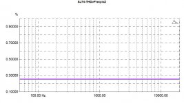
At low generator impedance, it is easy to drive the non-linear capacitance and the THD v Freq become flat.... two examples below, one JFET and one mosfet.
The other parts all show similar results - a flattening out of the THD.
When I get time I will show other results for these devices..
At low generator impedance, it is easy to drive the non-linear capacitance and the THD v Freq become flat.... two examples below, one JFET and one mosfet.
The other parts all show similar results - a flattening out of the THD.
When I get time I will show other results for these devices..
Attachments

Last edited:
The bandwidth of the fets (-3db) in order:
2SJ76: 45kHz
BSP: 38kHz
2SJ74: 35kHz
SJ313: 13kHz
The gain of the diff stage was also measured at the currents & loads mentioned earlier.
The Jfet J74 and the hitachi lateral mosfet 2SJ76 are similar.
But the have only HALF the gain versus the BSP and J313 fets!
2SJ76: 45kHz
BSP: 38kHz
2SJ74: 35kHz
SJ313: 13kHz
The gain of the diff stage was also measured at the currents & loads mentioned earlier.
The Jfet J74 and the hitachi lateral mosfet 2SJ76 are similar.
But the have only HALF the gain versus the BSP and J313 fets!
So the winner is..... ? 🙂
The laterals are known to have much lower non-linear capacitances.
Patrick
The laterals are known to have much lower non-linear capacitances.
Patrick
So the winner is..... ? 🙂
The laterals are known to have much lower non-linear capacitances.
Patrick
That is not evident in the graphs or measurements unfortunately ....
Last edited:
The capacitance v frequency is in the datasheet.
You can check that for yourself.
According to your posts #99 & 102, the 2J76 front end has the lowest distortion and highest bandwidth.
Not true ?
Probably lower noise with 2J74, but then this is power amp territory.
Patrick
You can check that for yourself.
According to your posts #99 & 102, the 2J76 front end has the lowest distortion and highest bandwidth.
Not true ?
Probably lower noise with 2J74, but then this is power amp territory.
Patrick
I don't see much in the renesas or hitachi datasheet except yfs vs freq at constant vds. The usual capacitance vs vds graphs are not there.
Yup the j76 has a larger bandwidth but distortion depends on where u look. The lateral has slightly better thd at mid freq but much worse at high freq.
Lateral has 0.15% thd at 1khz, 0.88% at 20khz
Fet has 0.2% thd at 1khz, and 0.6% at 20khz.
Lateral has half the transconductance too.
So on an objective basis i can't see the merits of the hitachi latfets for THIS application....
> So on an objective basis i can't see the merits of the hitachi latfets for THIS application....
I do.
The laterals has Yfs between JFET and Mosfet.
So you need to adapt the rest of the circuit accordingly.
And if THD is the only measure, we should all be building chip amps ......
Patrick
I do.
The laterals has Yfs between JFET and Mosfet.
So you need to adapt the rest of the circuit accordingly.
And if THD is the only measure, we should all be building chip amps ......
Patrick
> So on an objective basis i can't see the merits of the hitachi latfets for THIS application....
I do.
The laterals has Yfs between JFET and Mosfet.
So you need to adapt the rest of the circuit accordingly.
And if THD is the only measure, we should all be building chip amps ......
Patrick
I'm not sure i follow - your argument is that the hitachi laterals have poorer yfs than MOSFET but that makes them better ?
Last edited:
Mr. Pass,
I like to thank you in the name of all DIYers in the world for the time and attention you dedicate to us.
Even now you spent your time to review a project that is no longer in production and is used just for DIYers. THANK YOU VERY MUCH!!!
I beg you to excuse me for asking more from you. I know you are a very busy man and make very direct statements, but out here there are a lot of beginner DYIers like me, that need a more detailed lessons so we can follow your knowledge.
Please take some more time to explain the following doubts about the changes in the Aleph project:
1º. Why did you take out the CL60 as ground loop breaker? It was almost a standard in your projects. Can we take it out from all other projects too ?
2º Why to take out the over current protection? I know you said that’s an option, but I would like to know what made YOU take that decision. If I go this way I can take out Q104, R109 and R110 right?
3º R108 can be changed to 1K even if I stay using IRF9610? If the answer is yes, what is the purpose of almost three times the old value in this position?
One more time thank you
Regards
1º. Why did you take out the CL60 as ground loop breaker? It was almost a standard in your projects. Can we take it out from all other projects too ?
2º Why to take out the over current protection? I know you said that’s an option, but I would like to know what made YOU take that decision. If I go this way I can take out Q104, R109 and R110 right?
3º R108 can be changed to 1K even if I stay using IRF9610? If the answer is yes, what is the purpose of almost three times the old value in this position?
1) The CL60 is still there, I just moved the chassis ground to the other side
to comply with safety requirements.
2) It's hard to blow up the circuit without the protection, and nobody likes
to look at it (spoils the cow's milk), so I deleted it. Yes, those part #'s.
3) I don't see where R108 was changed. If you want offset adjustment
for different output Fets, you can use a 500 ohm or 1K pot, but 390
is still on the schematic.
About the Lateral Mosfets on the output, you can certainly use them. You
might want to try the Semelab Alfet ALF08N-16V and ALF08P-16V. If you
do, then by matching them you can eliminate R122 and R123. You might
also adjust or eliminate C104 and probably increase the gate stopper
resistors R116-119 to higher than the 221 ohms, maybe as high as 1K.
I haven't tried this, but adjustment for frequency stability and R108 would
be the only concerns, so you would want to own a scope.
😎
Mr. Pass, thank you for answering so fast.
I understood your answers for questions 1 and 2, they are clear to me now.
But my 3º question: “3º R108 can be changed to 1K even if I stay using IRF9610? If the answer is yes, what is the purpose of almost three times the old value in this position?”
You answered:
3) I don't see where R108 was changed. If you want offset adjustment
for different output Fets, you can use a 500 ohm or 1K pot, but 390
is still on the schematic.
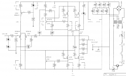
In the post #9 of this thread, in the first attached thumbnail you wrote “REPLACE R108 WITH 1K” just below the R108 position, and there wasn’t any talk about changing output Fets at that time, that was the reason of my doubt.
Please take a look and let me know if it was a mistake.
Thank you again for your kindness and patience with my questions.
Regards
I understood your answers for questions 1 and 2, they are clear to me now.
But my 3º question: “3º R108 can be changed to 1K even if I stay using IRF9610? If the answer is yes, what is the purpose of almost three times the old value in this position?”
You answered:
3) I don't see where R108 was changed. If you want offset adjustment
for different output Fets, you can use a 500 ohm or 1K pot, but 390
is still on the schematic.
In the post #9 of this thread, in the first attached thumbnail you wrote “REPLACE R108 WITH 1K” just below the R108 position, and there wasn’t any talk about changing output Fets at that time, that was the reason of my doubt.
Please take a look and let me know if it was a mistake.
Thank you again for your kindness and patience with my questions.
Regards
... In the post #9 of this thread, in the first attached thumbnail you wrote “REPLACE R108 WITH 1K” just below the R108 position...
That schematic has written on it "JFET INPUTS FOR ALEPH 3" so it's clear that those who want to use j74 or j109 at the input (with Id of about 5mA) should change R108 to 1k in order to provide adequate Vgs for Q108/109
Dear Juma, thank you for your interest but, what doesn't make it SO CLEAR is what is in post #16 and #17 in addition to Mr. Pass answer
"3) I don't see where R108 was changed. If you want offset adjustment
for different output Fets, you can use a 500 ohm or 1K pot, but 390
is still on the schematic"
You can CLEARLY SEE that he makes reference to different OUTPUT Fets and NOT input ones and he states that he "don't see where R108 was changed"
I see your point of view and maybe you can be right, but it is not clear at all and i would like to read a final word from Mr. Pass.
Regards
Dear nr12,
do you want me to get crazy?
Am I the only one that sees in the FIRST thumbnail in post #9 from Mr. Pass, right below the R108 the quote "REPLACE R108 WITH 1K" in capital letters?
Please check it and tell me that I am not seeing ghost.
Thank you for your interest.
Regards
do you want me to get crazy?
Am I the only one that sees in the FIRST thumbnail in post #9 from Mr. Pass, right below the R108 the quote "REPLACE R108 WITH 1K" in capital letters?
Please check it and tell me that I am not seeing ghost.
Thank you for your interest.
Regards
Ok, I did not notice it till now.
But all I read from this schematic is:
If you want to use 2sj109 as input fet, you should use 1k.
Regards
Ulf
But all I read from this schematic is:
If you want to use 2sj109 as input fet, you should use 1k.
Regards
Ulf
The confusion is over which schematic is being referenced.
The schematics of post #9 are correct.
The purpose of the higher value is to support the lower current that the
Jfet input needs due to dissipation limits. If you use a larger input device
you can run more current and have a lower value for R108.
😎
The schematics of post #9 are correct.
The purpose of the higher value is to support the lower current that the
Jfet input needs due to dissipation limits. If you use a larger input device
you can run more current and have a lower value for R108.
😎
Last edited:
- Home
- Amplifiers
- Pass Labs
- The Aleph Design Reloaded