that's change around Q3 (which is IRF9610), on sch. you posted
zener out ...... you see the rest
do not obsess with sound ....... no change in sound ........ noise will be decreased
if you have noise after that, you can freely toss those pcbs in garbage and find proper ones
zener out ...... you see the rest
do not obsess with sound ....... no change in sound ........ noise will be decreased
if you have noise after that, you can freely toss those pcbs in garbage and find proper ones
For now i have change 4,75k to 3.2k. But for this time no difrence at all. I will try ccs. Can i use bc560? It is on 45v.
Okey i will try next day, for now it is 12pm in poland,and im geting up on 410 Am. Very thanks for helping me.
Hello i have done ccs on bc560 and i have litle better than zener with 10uf cap. On my 97db speaker from 2 metres is quiet. It is pasible to do somethink else? You mentionen that i must twist cables from power supply to aleph pcb? What about 220uf caps near mpsa18? I have seen schematic with 470uf. And what about change 9610 on jfet? or irfp250n change to irfp244? pictures show noise with just a zenner with no cap, and a ccs.Very thanks
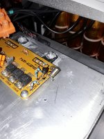
Attachments

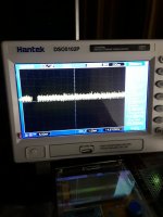
And i have measure that i have litle more voltage over 23v. On irfp250n i have 4,1v. On out 50mV. with zenner i have over 22v and 4.2v. On output over 15mV. So current i thinks is little less.
What resistor is from gain adjust? Mayby i will reduce gain? I dont need that much i have for now.
I'm asking - did you had same noise in both channels
I'm trying to deduce what cause of noise can be, either bad component (if only one channel being noisy) or systematic mistake (if both channels having same noise)
I'm trying to deduce what cause of noise can be, either bad component (if only one channel being noisy) or systematic mistake (if both channels having same noise)
redo the other channel with CCS I sketched and be happy with that
after that - try to find set of proper pcbs and make iteration with JFets on input (JFets available here in Store)
pcbs you have are most likely having some routing or even schmtc problem, in short - they're unreliable ( besides being sold as IP theft, unauthorized)
if you find pcbs on DIyaudio, you'll have confirmed and tested package, and no problems like you have with existing ones
and - it will sound better
Mayby i will reduce gain? I dont need big,
what is gain now ?
if you post schematic and write "these are values I actually have on pcb" then I can answer
for now, I can only guess - you have Pirated pcbs, and you posted partial schematic which Algar_Emi posted, as help for Aleph builders , many years ago
Lots off elements are same like on schematic i added. I will disolder some resistors and measire it. Please tell me with resistor(on this schematic) is adjusting gain? 750ohms? For now you help me much. But still dont have answers it is good idea do chage 9610 on jfets? Or change irfp250n on irfp244? Sory for hard work with me😉

gain is set to 10x
ratio of 10K (near red circle) and 1K (in red circle)
if you want lesser gain , decrease value of said 10K
if you read this tread from start, you'll have some clues and recipes how to make it better
no need to change output mosfets
in general, with JFet input (instead of TO220 mosfets) you'll get more detailed and more pleasant sound
look for Aleph J pcbs in Store and for P channel JFets (either original Toshiba or Linear Systems)
when done properly (any) Aleph is without hum and noise
Yes topic have lots lf informations. But some of them need more info, Like for example Mr Nelson have added schematic with little uprgraded pass3 ,like jfets and some resistors. But can i change resistor and still keep with 9610?
 Can i keep 9610 and replace 390ohm to 1k?
Jfet input is quiter than 9610? Sory for not precision questions and poor English
Jfet input is quiter than 9610? Sory for not precision questions and poor English
- Home
- Amplifiers
- Pass Labs
- The Aleph Design Reloaded