Hi Oliver,
I don't know how to proper mesure the T/S, maybe is not hard, but I'd like to measure frequency response first. Snake is the best Brazilian company for drivers and used to be very reliable, but we never know 😀
Do you have any documents about how to measure both of them?
Google how to measure t/s parameters with Room EQ wizard. All you need is a 30~100 ohm resistor, a mini-headphone to RCA cable and a couple of jumper cables.
Make sure that you "break in" the speaker before performing the measurement.
First of all, thanks for all suggestions. Sometimes there is not the best way but options and pros and cons.
I liked the dead space because it allows me to use it as grip to handle the cab so I made small changes on that area for this particular target 🙂
I think I used enough bracer, I see this all day at my works, and more bracer don't necessarily increase "body stiffness", sometimes it just increase weight and costs. This is the key for modern plastics components. To proof my cab design i should do FEM but it would take too much effort for it and I can trust on my experience in this case.
I'm really interested on this, could you provide more information and experience about it?
I would also try to clear additional information about cone correction once your have a lot of experience on this subject.
The compression ratio is linked to S1 or S2? sometimes it confuses me once many people say that adding cone correction will increase compression ratio and I don't want to change this characteristics from my design once the cone is not the stiffer one.
In addition, looks like the effect of adding cone correction is the same of increasing compression ratio, so is this really worth?
1st of all is to remove the "dead" space
I liked the dead space because it allows me to use it as grip to handle the cab so I made small changes on that area for this particular target 🙂
2nd is to use the bracing scheme
I think I used enough bracer, I see this all day at my works, and more bracer don't necessarily increase "body stiffness", sometimes it just increase weight and costs. This is the key for modern plastics components. To proof my cab design i should do FEM but it would take too much effort for it and I can trust on my experience in this case.
Finally, consider inserting damping material into the section of the horn as illustrated - this will reduce the ripple above the passband with minimum impact in the TH's passband.
I'm really interested on this, could you provide more information and experience about it?
I would also try to clear additional information about cone correction once your have a lot of experience on this subject.
The compression ratio is linked to S1 or S2? sometimes it confuses me once many people say that adding cone correction will increase compression ratio and I don't want to change this characteristics from my design once the cone is not the stiffer one.
In addition, looks like the effect of adding cone correction is the same of increasing compression ratio, so is this really worth?
I think I used enough bracer, I see this all day at my works, and more bracer don't necessarily increase "body stiffness", sometimes it just increase weight and costs. This is the key for modern plastics components. To proof my cab design i should do FEM but it would take too much effort for it and I can trust on my experience in this case.
Have a look at the bracing I used here - The Subwoofer DIY Page v1.1 - Projects : "Proof of Concept #3". And it wasn't enough. I ended up having to double the panel thickness at the top of the TH to kill vibration. And that's 18mm ply with 12mm thick ply used for the braces. And this is a TH based on a 12" driver. As it's difficult to adjust bracing in this location of the horn after the horn's all buttoned up, overkill here might be better than underkill 🙂.
I'm really interested on this, could you provide more information and experience about it?
The effect can be modelled in Hornresp - just increase S1 and keep S2 unchanged, then use the "Filling" option under the HornResp's Loudspeaker Wizard feature to sim the impact of stuffing the first 75% or so of S1-S2. Experiment with the amount of stuffing in the sim.
The compression ratio is linked to S1 or S2? sometimes it confuses me once many people say that adding cone correction will increase compression ratio and I don't want to change this characteristics from my design once the cone is not the stiffer one.
The compression ratio is linked to S2. "Cone compensation" basically compensates for the volume contained by the driver's cone and basically can be sim'd in HornResp by setting (or leaving) Vtc=0. If you do NOT include cone compensation in your build, then you should set Vtc to the same volume as that contained by the driver's cone and also the volume occupied by the cutout for the driver in the horn.
The effect can be modelled in Hornresp
I can't change S1 once the woods are already cut, but i tried to use filling tools but see no difference.
The compression ratio is linked to S2
This change many things, so my first post is wrong for CR and many others posts I read from others threads too, maybe the confusion happens when you think about FLH and in that case the CR would be SD/S1, but for TH once the drivers are off-setted the equation became SD/S2.
Once my target is CR 2:1 I must do cone correction to reach it and get the benefits otherwise the CR would be lower: 880/500=1,76
If the benefits are small or big is a different story
Below the is frequency response with and without cone correction for who wants to see the difference. PS.: The red area is what you gain with cone correction.
An externally hosted image should be here but it was not working when we last tested it.
One more phase completed yesterday:
Rectangular cuts = Done
Angle cuts = Done
Cone corrector + Bracers + Bafle = Done
PS.: I'm using different wood for the cone corrector, one with lower density compared to polywood.
Direct image link: https://s12.postimg.org/jgz33vswd/Cone_corrector.jpg
Direct image link: https://s13.postimg.org/t0jnw3f9z/bracers.jpg
Direct image link: https://s9.postimg.org/40p2cpdof/Bafles.jpg
Rectangular cuts = Done
Angle cuts = Done
Cone corrector + Bracers + Bafle = Done
PS.: I'm using different wood for the cone corrector, one with lower density compared to polywood.
An externally hosted image should be here but it was not working when we last tested it.
Direct image link: https://s12.postimg.org/jgz33vswd/Cone_corrector.jpg
An externally hosted image should be here but it was not working when we last tested it.
Direct image link: https://s13.postimg.org/t0jnw3f9z/bracers.jpg
An externally hosted image should be here but it was not working when we last tested it.
Direct image link: https://s9.postimg.org/40p2cpdof/Bafles.jpg
Back to post some updates.
As usual I'm asking for some help. This is the first time I'm using T-nuts, is there any experience about it? should I glue it or just trust on the spikes?
Regarding the project itself I made a nice progress this weekend. take a look.
PASC suggested me in a private message to apply chemical product against termite at cone corrector, so I did it. Low density woods used to be a dessert for this inset.
As you can see at the baffle I'm using some reinforcement to improve stiffness, sometimes bracer is better but some ribs can do the job if you install it at the right place.
PS.: I feels like doing serial production 😀
Direct image link: https://s11.postimg.org/e1nh2z0k3/image.jpg
Sirect image link: https://s27.postimg.org/7h1whdlz7/image.jpg
Direct image link: https://s24.postimg.org/9uoah19hx/image.jpg
Direct image link: https://s7.postimg.org/xig1buo57/image.jpg
Direct image link: https://s21.postimg.org/dyb3vx9av/image.jpg
Direct image link: https://s11.postimg.org/46pccg8qb/image.jpg
Direct image link: https://s13.postimg.org/k11j1qiyf/image.jpg
Direct image link: https://s11.postimg.org/aeu1ho6qr/image.jpg
Direct image link: https://s27.postimg.org/pzww9qear/image.jpg
As usual I'm asking for some help. This is the first time I'm using T-nuts, is there any experience about it? should I glue it or just trust on the spikes?
Regarding the project itself I made a nice progress this weekend. take a look.
PASC suggested me in a private message to apply chemical product against termite at cone corrector, so I did it. Low density woods used to be a dessert for this inset.
As you can see at the baffle I'm using some reinforcement to improve stiffness, sometimes bracer is better but some ribs can do the job if you install it at the right place.
PS.: I feels like doing serial production 😀
An externally hosted image should be here but it was not working when we last tested it.
Direct image link: https://s11.postimg.org/e1nh2z0k3/image.jpg
An externally hosted image should be here but it was not working when we last tested it.
Sirect image link: https://s27.postimg.org/7h1whdlz7/image.jpg
An externally hosted image should be here but it was not working when we last tested it.
Direct image link: https://s24.postimg.org/9uoah19hx/image.jpg
An externally hosted image should be here but it was not working when we last tested it.
Direct image link: https://s7.postimg.org/xig1buo57/image.jpg
An externally hosted image should be here but it was not working when we last tested it.
Direct image link: https://s21.postimg.org/dyb3vx9av/image.jpg
An externally hosted image should be here but it was not working when we last tested it.
Direct image link: https://s11.postimg.org/46pccg8qb/image.jpg
An externally hosted image should be here but it was not working when we last tested it.
Direct image link: https://s13.postimg.org/k11j1qiyf/image.jpg
An externally hosted image should be here but it was not working when we last tested it.
Direct image link: https://s11.postimg.org/aeu1ho6qr/image.jpg
An externally hosted image should be here but it was not working when we last tested it.
Direct image link: https://s27.postimg.org/pzww9qear/image.jpg
Nice job on the cutting.
Mostly I glue the T-nuts or just two flat screw to prevent it from being pushed out.
The problem of T-nuts loosing and falling out is caused by pushing on the drill to loosen or tighten the bolt into the T-nut.
Or use machine head stud with a reverse thread. Hard to find the right one but with this you just drop the driver over the pins and done.
I meant these things.
Last edited:
Hello guys,
Slowly I'm progressing 😀
Posting some updates today that contain some build details. There are small differences regarding the posted design but I will update the 3D as Built 🙂
Direct image link: https://s24.postimg.org/jinekohfp/image.jpg
Direct image link: https://s8.postimg.org/f8y8koiyt/image.jpg
Direct Image link: https://s27.postimg.org/qezg0m9b7/image.jpg
Direct image link: https://s1.postimg.org/x8vikb9bj/image.jpg
Direct image link: https://s8.postimg.org/8m5dhvm11/image.jpg
Direct image link: https://s10.postimg.org/xb85obrc9/image.jpg
Direct image link: https://s28.postimg.org/szfadbhul/image.jpg
Direct image link: https://s27.postimg.org/dlqu93qur/image.jpg
Slowly I'm progressing 😀
Posting some updates today that contain some build details. There are small differences regarding the posted design but I will update the 3D as Built 🙂
An externally hosted image should be here but it was not working when we last tested it.
Direct image link: https://s24.postimg.org/jinekohfp/image.jpg
An externally hosted image should be here but it was not working when we last tested it.
Direct image link: https://s8.postimg.org/f8y8koiyt/image.jpg
An externally hosted image should be here but it was not working when we last tested it.
Direct Image link: https://s27.postimg.org/qezg0m9b7/image.jpg
An externally hosted image should be here but it was not working when we last tested it.
Direct image link: https://s1.postimg.org/x8vikb9bj/image.jpg
An externally hosted image should be here but it was not working when we last tested it.
Direct image link: https://s8.postimg.org/8m5dhvm11/image.jpg
An externally hosted image should be here but it was not working when we last tested it.
Direct image link: https://s10.postimg.org/xb85obrc9/image.jpg
An externally hosted image should be here but it was not working when we last tested it.
Direct image link: https://s28.postimg.org/szfadbhul/image.jpg
An externally hosted image should be here but it was not working when we last tested it.
Direct image link: https://s27.postimg.org/dlqu93qur/image.jpg
Last edited:
Looking forward to seeing the completed project. Did you say there was a 3d available? Great work so far.
Yeah, the 3D model is available, but i will updated it "as built" soon.
Here are some updates.
All 4 cabs are completely assembled and the finishing process just started.
The brown colored faces received a "think" to correct the surfaces before the paint, it's not a primer, it's specific product for woods but I don't know the name in english. It also help to eliminate small misalignments.
Other then that, I applied chemical sealing internally and externally, i mean, the glue used to unity the pieces also sealed the edges, but in this case, this sealing is specific for surfaces to close wood porosity before paint of before apply other substances, it also helps a lot to protect against water that is very important for tropical countries like Brazil.
I'm very proud of my grip, it's very efficient and beautiful. There is a zoom to see some detail.
I can't wait to show you all the final results but it will take some time.
Note: this project consumed so many screws 😱 , the amount was around 280units/cab
Direct image link: https://s11.postimg.org/c25hp1m5v/screws.jpg
Direct image link: https://s30.postimg.org/4nm394xbl/cab.jpg
Direct image link: https://s22.postimg.org/wl5kjmo4x/finishing.jpg
Direct image link: https://s16.postimg.org/cv9n6pkhh/grip.jpg
Here are some updates.
All 4 cabs are completely assembled and the finishing process just started.
The brown colored faces received a "think" to correct the surfaces before the paint, it's not a primer, it's specific product for woods but I don't know the name in english. It also help to eliminate small misalignments.
Other then that, I applied chemical sealing internally and externally, i mean, the glue used to unity the pieces also sealed the edges, but in this case, this sealing is specific for surfaces to close wood porosity before paint of before apply other substances, it also helps a lot to protect against water that is very important for tropical countries like Brazil.
I'm very proud of my grip, it's very efficient and beautiful. There is a zoom to see some detail.
I can't wait to show you all the final results but it will take some time.
Note: this project consumed so many screws 😱 , the amount was around 280units/cab
An externally hosted image should be here but it was not working when we last tested it.
Direct image link: https://s11.postimg.org/c25hp1m5v/screws.jpg
An externally hosted image should be here but it was not working when we last tested it.
Direct image link: https://s30.postimg.org/4nm394xbl/cab.jpg
An externally hosted image should be here but it was not working when we last tested it.
Direct image link: https://s22.postimg.org/wl5kjmo4x/finishing.jpg
An externally hosted image should be here but it was not working when we last tested it.
Direct image link: https://s16.postimg.org/cv9n6pkhh/grip.jpg
Let me take again advantage of the forum knowledge again and ask you guys for some suggestion for mid-bass (the next bandwidth)
Target:
Driver data:
I've been using vented box (376x340x290 = 37L), but I'm open mind to improved it if something new for me comes out of the light.
Direct image link: https://s23.postimg.org/6csgq1z2j/10cab.png
Target:
Frequency response: from 100Hz to 2000Hz
Low volume as possible
Use #1 10" driver / cab
Total of cabs = 4
Low volume as possible
Use #1 10" driver / cab
Total of cabs = 4
Driver data:
Driver brand: Snake
Model: ESX310
fs = 67 Hz
Re = 5 ohm
Qms = 6,653
Qes = 0,192
Qts = 0,186
Vas = 28 L
Sd = 0,0314 m^2
Xmax = 4 mm
Le = 0,28 mH
BL = 17,37 T/m
no = 4,3%
Mms = 28 g
Model: ESX310
fs = 67 Hz
Re = 5 ohm
Qms = 6,653
Qes = 0,192
Qts = 0,186
Vas = 28 L
Sd = 0,0314 m^2
Xmax = 4 mm
Le = 0,28 mH
BL = 17,37 T/m
no = 4,3%
Mms = 28 g
I've been using vented box (376x340x290 = 37L), but I'm open mind to improved it if something new for me comes out of the light.
An externally hosted image should be here but it was not working when we last tested it.
Direct image link: https://s23.postimg.org/6csgq1z2j/10cab.png
Hello all,
Finally I finished the cabs, thanks all to help me in this journey. I hope the result is praiseworthy, I've been posting as much details as I can.
I'm very proud of the grips I developed, I never saw one that looks like it and it's very comfortable. I'm a tall guy with a big hand so you can see a photo
in detail about it. The red carpet also introduces a cool visual effect.
The cab finishing is made in carpet, I like it, it gives sophisticate finishing, when you stack cabs they grips strongly and if you put it on the floor they never walk, you don't need rubber feet.
To easy move the cabs I put the wheels separately on what I named as "Skate".
Regarding the sounds, I like it, but I made just a fast test, I still need to set up my DSP and do proper aliment. The only cons for a while is the driver venting noise as a lot of guys mention at their projects, but no worries, my old T18 were the same.
Note: Just two cabs have driver for a while.
When I'm ready I will measure and share the Frequency Response but unfortunately I'm not able to measure driver's T/S parameter nether cab impedance. When the Real/Dolar rate improves I will try to buy Dayton Audio DATS V2 but no promises.
The grills are made in textile, I still need to find good supplier for metallic one.
Direct image link: https://s7.postimg.org/aakfauexn/image.jpg
Direct image link: https://s11.postimg.org/8iwf1zcxv/image.jpg
Direct image link: https://s29.postimg.org/5ofrgd9o7/image.jpg
Direct image link: https://s9.postimg.org/mp7kv7u67/image.jpg
Direct image link: https://s2.postimg.org/gfxt7w25l/image.jpg
Direct image link: https://s22.postimg.org/9qejc6o41/image.jpg
Direct image link: https://s14.postimg.org/ct11wq9q9/image.jpg
Direct image link: https://s29.postimg.org/jibndf1s7/image.jpg
Direct image link: https://s3.postimg.org/dfplucr6b/image.jpg
Direct image link: https://s17.postimg.org/h5dxgzwdb/image.jpg
Direct image link: https://s7.postimg.org/z52vxatsr/image.jpg
Direct image link: https://s7.postimg.org/5vlzkb3wr/image.jpg
Direct image link: https://s16.postimg.org/5qhuw1skl/image.jpg
Direct image link: https://s15.postimg.org/gjcn6y6wr/image.jpg
Direct image link: https://s3.postimg.org/fwarhj5gj/image.jpg
Direct image link: https://s29.postimg.org/9adcll4nr/image.jpg
Direct image link: https://s11.postimg.org/kk0nazlj7/image.jpg
Finally I finished the cabs, thanks all to help me in this journey. I hope the result is praiseworthy, I've been posting as much details as I can.
I'm very proud of the grips I developed, I never saw one that looks like it and it's very comfortable. I'm a tall guy with a big hand so you can see a photo
in detail about it. The red carpet also introduces a cool visual effect.
The cab finishing is made in carpet, I like it, it gives sophisticate finishing, when you stack cabs they grips strongly and if you put it on the floor they never walk, you don't need rubber feet.
To easy move the cabs I put the wheels separately on what I named as "Skate".
Regarding the sounds, I like it, but I made just a fast test, I still need to set up my DSP and do proper aliment. The only cons for a while is the driver venting noise as a lot of guys mention at their projects, but no worries, my old T18 were the same.
Note: Just two cabs have driver for a while.
When I'm ready I will measure and share the Frequency Response but unfortunately I'm not able to measure driver's T/S parameter nether cab impedance. When the Real/Dolar rate improves I will try to buy Dayton Audio DATS V2 but no promises.
The grills are made in textile, I still need to find good supplier for metallic one.
An externally hosted image should be here but it was not working when we last tested it.
Direct image link: https://s7.postimg.org/aakfauexn/image.jpg
An externally hosted image should be here but it was not working when we last tested it.
Direct image link: https://s11.postimg.org/8iwf1zcxv/image.jpg
An externally hosted image should be here but it was not working when we last tested it.
Direct image link: https://s29.postimg.org/5ofrgd9o7/image.jpg
An externally hosted image should be here but it was not working when we last tested it.
Direct image link: https://s9.postimg.org/mp7kv7u67/image.jpg
An externally hosted image should be here but it was not working when we last tested it.
Direct image link: https://s2.postimg.org/gfxt7w25l/image.jpg
An externally hosted image should be here but it was not working when we last tested it.
Direct image link: https://s22.postimg.org/9qejc6o41/image.jpg
An externally hosted image should be here but it was not working when we last tested it.
Direct image link: https://s14.postimg.org/ct11wq9q9/image.jpg
An externally hosted image should be here but it was not working when we last tested it.
Direct image link: https://s29.postimg.org/jibndf1s7/image.jpg
An externally hosted image should be here but it was not working when we last tested it.
Direct image link: https://s3.postimg.org/dfplucr6b/image.jpg
An externally hosted image should be here but it was not working when we last tested it.
Direct image link: https://s17.postimg.org/h5dxgzwdb/image.jpg
An externally hosted image should be here but it was not working when we last tested it.
Direct image link: https://s7.postimg.org/z52vxatsr/image.jpg
An externally hosted image should be here but it was not working when we last tested it.
Direct image link: https://s7.postimg.org/5vlzkb3wr/image.jpg
An externally hosted image should be here but it was not working when we last tested it.
Direct image link: https://s16.postimg.org/5qhuw1skl/image.jpg
An externally hosted image should be here but it was not working when we last tested it.
Direct image link: https://s15.postimg.org/gjcn6y6wr/image.jpg
An externally hosted image should be here but it was not working when we last tested it.
Direct image link: https://s3.postimg.org/fwarhj5gj/image.jpg
An externally hosted image should be here but it was not working when we last tested it.
Direct image link: https://s29.postimg.org/9adcll4nr/image.jpg
An externally hosted image should be here but it was not working when we last tested it.
Direct image link: https://s11.postimg.org/kk0nazlj7/image.jpg
The only difference related to the shared plan was some additional reinforcement to the back panel.
Take a look at the complete reinforcement picture.
Direct image link: https://s15.postimg.org/469wuejmj/as_Built.png
Take a look at the complete reinforcement picture.
An externally hosted image should be here but it was not working when we last tested it.
Direct image link: https://s15.postimg.org/469wuejmj/as_Built.png
Thanks.
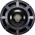
There is a venting area at driver's back, See red rectangle. I don't think it will be a problem, the previous cab i had used the same driver brand with the same solution and wans't a issue, but if you go closer you can ear it.
Direct image link: https://s18.postimg.org/yze866i6x/Snake-_HPX2150_2.jpg
There is a venting area at driver's back, See red rectangle. I don't think it will be a problem, the previous cab i had used the same driver brand with the same solution and wans't a issue, but if you go closer you can ear it.
An externally hosted image should be here but it was not working when we last tested it.
Direct image link: https://s18.postimg.org/yze866i6x/Snake-_HPX2150_2.jpg
That's the pole piece. No wonder it makes noise. The vent looks smaller than the actual pole piece diameter.
- Home
- Loudspeakers
- Subwoofers
- TH 15" flat response to 35Hz (-3dB) - By LORDSANSUI