Member
Joined 2009
Paid Member
Hi tvi, I recognize that topology !
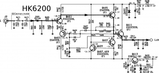
The HK6200 adds a simple emitter follower to get a better output impedance; Salas does something similar, using a single JFET instead of a BJT - I'm using cascaded emitter followers for my buffer so not too different.
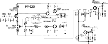
The PM625 makes up a bipolar output capacitor from two polarized units - I'll use an off-the-shelf bipolar for that.
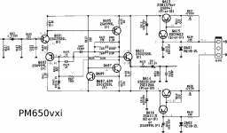
And the PM650 using a Sziklai capacitance multiplier for regulation with better Zout.
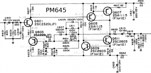
Its interesting to see that this general topology has seen a lot more use than I had known about.
The HK6200 adds a simple emitter follower to get a better output impedance; Salas does something similar, using a single JFET instead of a BJT - I'm using cascaded emitter followers for my buffer so not too different.
The PM625 makes up a bipolar output capacitor from two polarized units - I'll use an off-the-shelf bipolar for that.
And the PM650 using a Sziklai capacitance multiplier for regulation with better Zout.
Its interesting to see that this general topology has seen a lot more use than I had known about.
Although I doubt this is helpful, not using a buffer sometimes is the best sound one can have. I remember being very pleasently surprised by the sound of a Leak Varislope and Stereo 20 my brother had just serviced. Much like the best transistor amps although valve. Functional complexity with only 2 x EF 86 valves ( 4 total in the preamp ). Nearly every rule I held to be true was broken. Pentode valves, negative feedback a plenty. Gradually it got through to me why it worked. Someone had devoted lots of thinking to the circuit. The genius touch which at first I thought was a custormer bodge up was a very short piece of TV coax from pre to power amp. The anode ( high z ) output to the ideally judged input of the power amp via the coax ( circa 30 pF ). The distortion was very low and the hiss and hum not bad. The facilities were/are the very best for playing pre 1960's back to 1920's discs. The RIAA by shunt feedback ( active ). As my brother pointed out the RIAA was done by " fiddle factor " in most valve designs ( and early transistor ). That is as best as possible the gain dropping was tweaked into the time constants. The whole point was to get the job done with as little active circuitry as possible to reduce costs.
I recently heard my friends Leak combo see off her Krell set up. She being a musician and ex BBC sound engineer she isn't give to hype, she preferes the Leak. To be frank the Leak is more accurate. It allows the way music unfolds to be more obvious. PRaT as if Naim is excellent. The Quad 2/22 although " very nice " isn't my cup of tea. I sometimes think the Leak by doing the cheaper thing did it better. Regardless of the silly money KT66 the Leaks EL84's are my cup of tea.
I recently heard my friends Leak combo see off her Krell set up. She being a musician and ex BBC sound engineer she isn't give to hype, she preferes the Leak. To be frank the Leak is more accurate. It allows the way music unfolds to be more obvious. PRaT as if Naim is excellent. The Quad 2/22 although " very nice " isn't my cup of tea. I sometimes think the Leak by doing the cheaper thing did it better. Regardless of the silly money KT66 the Leaks EL84's are my cup of tea.
Member
Joined 2009
Paid Member
If a buffer is not needed I'd be happy to leave it off. My concern with the high Zout of the phono amp is that it will have to drive a volume pot and where the Zout is highest is below 100Hz so we quickly lose bass response.
Whilst tube amps typically have high Z volume pots (100K and above) I have noticed that this is not favoured in SS because low Z volume pots can have lower noise.
A buffer lowers the Zout of the phono so that it is comparable to the drive capability of other source components that I'll connect to the line inputs. That way the volume pot can be 10k ohm or less. Well, at least this was my thinking behind the schematic I posted.
Last edited:
Member
Joined 2009
Paid Member
This approach is somewhat out of fashion, especially with the popularity of SETs. However, funny you should mention. I have a tube project waiting in the wings. It is a Pentode amp with feedback. The circuit is copied from a well regarded Shindo amplifier that I was able to obtain the schematic and build details for. I don't have the same valves available though, as he used some rare beasts that I believe are now unobtainium.Pentode valves, negative feedback a plenty.
I think that's what I would say. However there are times when to do the better thing is possible. I guess one reason to make the output buffer a gain of one is so that the passive option can be had by a jumper cable. I could see an arguement to make the power amp J FET input to help this.
Can anyone answer this. I see the various uses and use JFET devices myself. By analogy with valves they set conditions via a bias voltage to the gate of a depletion device. And yet bias current is near zero. Is it the difference between near zero and actual zero that allows it to work? One never questions the DC offset of a TL071 to be not far from a NE5534. A JFET can not be exactly be a capacitor who's field limits it's current flow. I guess like valves there is a stated current flow?
Can anyone answer this. I see the various uses and use JFET devices myself. By analogy with valves they set conditions via a bias voltage to the gate of a depletion device. And yet bias current is near zero. Is it the difference between near zero and actual zero that allows it to work? One never questions the DC offset of a TL071 to be not far from a NE5534. A JFET can not be exactly be a capacitor who's field limits it's current flow. I guess like valves there is a stated current flow?
This approach is somewhat out of fashion, especially with the popularity of SETs. However, funny you should mention. I have a tube project waiting in the wings. It is a Pentode amp with feedback. The circuit is copied from a well regarded Shindo amplifier that I was able to obtain the schematic and build details for. I don't have the same valves available though, as he used some rare beasts that I believe are now unobtainium.
That would be worth a thread. Get some of the Naim guys to join in I hope. I have done tons of hours on this style of amp. Although he was banned from here Alex Kitic is a logical thinker except too much in love with his own designs. He is fine with me when I write to him. I always give in when he doesn't like my ideas as he usually he is right from a narrower perspective than I might have. The RH ideas were typical of 807's amps in 1938 ( Fender, Schade, RCA ). It is highly valid to attempt shunt feedback this way and make a super output pair. Kitic has the Rp of a " triode " strapped pentode as 1K2. In his super shunt he has 900R. I have measured this and think he has a point. The Kitic amps work a bit like a transistor VAS of the older school. Personally I like UL feedback without too much loop feedback( zero perhaps ). 80% triode UL is interesting.
RH Amplifiers: RH Universal
http://www.electronics-tutorials.ws/transistor/tran_5.htmlCan anyone answer this. I see the various uses and use JFET devices myself. By analogy with valves they set conditions via a bias voltage to the gate of a depletion device. And yet bias current is near zero. Is it the difference between near zero and actual zero that allows it to work? One never questions the DC offset of a TL071 to be not far from a NE5534. A JFET can not be exactly be a capacitor who's field limits it's current flow. I guess like valves there is a stated current flow?
The gate current is just a leakage current. If the gate is properly insulated it becomes an IGFET or MOSFET.
You can think of a JFET input as a small capacitor that charge has to be changed in to change the electric field and thus change the effective resistance of the DS channel. The GS may have very high dc resistance but it still needs charging up and down for ac.
I have always assumed that. A valve has it's parts on display so guessing is not really required.
Member
Joined 2009
Paid Member
I have the same attitude towards BJTs too, it's not a current controlled device, the base current is a parasitic property of the device and should not be relied on for a design.The gate current is just a leakage current.
Member
Joined 2009
Paid Member
Do remind me. That's also an incentive to get this pre-amp built - there's always another project 🙂That would be worth a thread. Get some of the Naim guys to join in I hope. I have done tons of hours on this style of amp.
So I'll spend some time to make a first draft layout for Board #1 now that the content of it is more settled in my mind. Any feedback on the schematic is welcome of course.
Board#2 will be next up. This one should have the NAIM-style gain stage option and the output buffer. The original NAIM gain stage runs off 24V, single rail. I think it can be converted easily to dual-rail to maximize headroom. The output buffer - I would still be very tempted to use the Super Linear Diamond Buffer that I posted earlier in this thread - it's a really nice circuit on account of very low distortion, high bandwidth, high PSRR and good drive capability - all without loop feedback. Does it also have to be capable of driving headphones, or does this compromise the design as a good line-driver ? And IF it is to be capable of driving headphones then we're talking much more current so a shunt regulator might be too greedy so a series regulator will be the choice (Op-amps are allowed, but discrete is so much more fun to design!).
Last edited:
Huh. Well that's just silly. 😀I have the same attitude towards BJTs too, it's not a current controlled device, the base current is a parasitic property of the device and should not be relied on for a design.
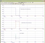
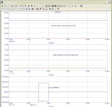
I had another play with this last night. I've uploaded the LTSpice file, ......
Hi Gareth, apologies for asking, why use a shunt regulator with a class A pre-amp, it is a shunt in its own right.
If the pre-amp is class A/B, this regulator behaves very poorly under transient conditions regardless of its apparent "low output impedance".
With very limited knowledge of your power requirement, an LM337/317 could provide far better results.
Member
Joined 2009
Paid Member
The phono amp + buffer should always be operating in Class A, there's no expectation of a load impedance so low as to force it into Class AB at the design bias levels. But it's push-pull so there will be signal currents on the rails. The circuit is not an effective shunt in itself - it has very poor PSRR and does not flow current symmetrically through the rails. The current flowing from the positive rail will return partly through the 'ground' and partly through the negative rail.
The poor PSRR makes it important to have a very solid supply, something that will stay out of the way audibility-wise (low rail impedance across the audio range implies a feedback based regulator) and low noise. The current levels are low so a shunt regulator is feasible and also capable of delivering good results.
I didn't try a square-wave simulation, that looks interesting. I don't want ringing on the supply rails, perhaps it will be necessary to take some additional precautions.
Are you thinking that a simple cap-multiplier + rail caps is going to perform better ? or that it will perform as good without the complexity ?
I am concerned about subjective reports from others that have mentioned they do not like the sound of circuits running from cap-multipliers (one of your friends, Hugh, says such a thing too). I remember reading somewhere on this forum that Nelson says to use 'lots of capacitance' after the multiplier so that signals don't flow through the multiplier. All that capacitance (you need a lot to get down to low frequencies with low impedance) is effectively a passive shunt regulator and good quality capacitors are needed to keep them inaudible. On the other hand, there are plenty of favourable reports from folk using shunt regulators with their phono stages (Salas simplistic).
Last edited:
Do remind me. That's also an incentive to get this pre-amp built - there's always another project 🙂
It goes without saying, if a unity gain buffer, diamond or otherwise add any distortion at all, it should not even be considered. A buffer should only increase current drive, still following the input signal faithfully.
Member
Joined 2009
Paid Member
Hi Nico - I'm not able to understand how to link your buffer distortion comment with that quote of mine about a future tube-amp project. But I certainly agree with your guidance there regarding buffer distortion. The one I've chosen does very well in simulations. I believe real-life performance will also be very good because of two things, first the rather small signal levels compared with the rail voltage and second, only having to drive a relatively high impedance - something like a 5k volume pot - with an output impedance that's 100 times smaller.
Gareth I am sorry, I only see now that your series resistance is 1,8 ohm and not 18 ohm, this make an order of magnitude improvement. Your second schematic is also considerably better than the first, I did not keep track of your changes since there was no further discussion back then. However, now you know someone is checking up on you. 🙂 🙂
I deleted my previous comment as it was untrue.
I deleted my previous comment as it was untrue.
Last edited:
Hi Nico - I'm not able to understand how to link your buffer distortion comment.....
Gareth, I simply made a comment which actually supported your and other members, probably not using such clever speech, 🙂
I meant that a buffer should not add any artifacts nor amplify artifacts from the previous stage (unity gain), it should just transform to a lower (or higher) impedance while not loading the preceding stage in any way that it changes its frequency/amplitude or phase response.
Buffers seem like simple things but they are really quite a mouthful and are necessary in circuits that you are unaware of what follows, for instance in commercial audio where the power amp from some manufacturer could load the pre-amp from another species with a few ohms in stead of a few thousand ohms.
So let me recap - don't use buffers if you are designing for your own products, it is not necessary. Make the pre-amp work with the main amp from the outset you don't cater for the masses. In other words, design them, simulate and test them as a unit not as two separate unrelated items. 😀 Make an "integrated amp" from the outset not separates as they became known. That is even more the reason that a Niam, Linn, Quad, McIntosh, etc sounded right because they were meant to match amp and pre-amp. Anything mixed was never a match it was a compromise and a figment of the audiophools imagination that they could match different products together and the designer could not because he/she was plain stupid.
I would suggest you draw your system as a single schematic and then you know exactly what to expect from it.
Last edited:
- Status
- Not open for further replies.
- Home
- Source & Line
- Analog Line Level
- TGMC - a modular control pre-amplifier