It's probably just a FET'ish.Some say JFET's sound better due to amplification curves. I have doubts about that.
The Naim stuff doesn't always look the business but it sounds good.I was looking again at the NAC gain stage. It's not a bad design at all.
I sometimes use a 10k volume pot to directly drive my amplifiers (for the convenience of others) and sometimes I drive my amplifiers directly from my DAC. The passive pot is fine and probably won't be the limiting factor of your system's sound quality. However, the relatively high impedance will have a small, detrimental effect so, yes, add a switchable-in-able buffer. Why not?If I put this all in front of a 1k, 5k or 10k ohm volume pot it could be quite simple. There would be no need for a buffer after the volume pot if it were low enough impedance ?
The simplest case becomes: source select -> (optional NAC gain/buffer stage) -> vol. pot -> line out
However, there are many subjective reports about improved sound from the use of an active buffer to drive Line Out so it is quite tempting to want to retain one.
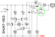
I have a few questions about Q207 in the schematic attached to post #320 (copied below)
1. What is the worst-case scenario that causes the very highest power dissipation within Q207 ?
2. Numerically, what is the very highest possible power dissipation in Q207 ?
3. Which SMD packages are rated to handle Q207's max possible power dissipation, comfortably? Which SMD packages absolutely cannot handle Q207's max possible power dissipation?
4. Which thru-hole packages are suitable for Q207's max power? Which thru-hole packages are unsuitable?
_
1. What is the worst-case scenario that causes the very highest power dissipation within Q207 ?
- Power switch-on?
- Power switch-off?
- Charging up all downstream capacitors from 0V to 30V?
- Downstream fault that shorts output to GND?
- Output not connected to any downstream load?
- High temperature?
- Some combination of the above?
2. Numerically, what is the very highest possible power dissipation in Q207 ?
3. Which SMD packages are rated to handle Q207's max possible power dissipation, comfortably? Which SMD packages absolutely cannot handle Q207's max possible power dissipation?
4. Which thru-hole packages are suitable for Q207's max power? Which thru-hole packages are unsuitable?
_
Attachments
Last edited:
Member
Joined 2009
Paid Member
I didn't look too carefully at the corner cases on Q207 but I can't see it dissipating very much power at all, very little actually. You may be asking because I chose a TO-126 part. My thought behind this choice is that it's convenient to mount on the heatsink along with the main pass transistor Q201. There is some benefit in having them thermally coupled for stable current supply - overkill but it costs me so little.
Output current equals (VBE_Q207 / R201).
If you want output current to be constant and independent of temperature, you can either
Thermally coupling the control transistor Q207 to the pass transistor Q201 makes the output current variation bigger, not smaller.
If you want output current to be constant and independent of temperature, you can either
* Choose an R201 which has the same temperature coefficient as VBE_Q207 (about -3000 ppm per degree K) and thermally bond them together to guarantee they are always at the same temperature. There don't seem to be any thru hole resistors with that tempco; in SMD you could use the Panasonic ERAS, ERAW, ERAV
* Find a way to operate Q207 at constant temperature, independent of supply voltage, independent of load current, independent of the temperatures of the other transistors. And operate R201 at constant temperature as well.
* Find a way to operate Q207 at constant temperature, independent of supply voltage, independent of load current, independent of the temperatures of the other transistors. And operate R201 at constant temperature as well.
Thermally coupling the control transistor Q207 to the pass transistor Q201 makes the output current variation bigger, not smaller.
Member
Joined 2009
Paid Member
Good catch Mark ! - in this case, I would change Q207 to a TO-92 device and leave it free-standing, not on the heatsink. How did I get to this point ? - I used a diode + bjt current source in another project and thermal control was better with the diodes and bjt coupled. However, that was a different circuit. So far, in this project, I haven't used SMD transistors. I have some in my junk box but it hasn't crossed my mind to use them here (yet).
Member
Joined 2009
Paid Member
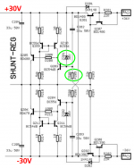
zener will be small SMD. The load resistor is the old value, when it was to ground. My LTSpice file has it at 33k.
Another resistor that hasn't had any thought is the current mirror degeneration. I picked 10R out of a hat - seems a common value but there was not science behind this choice on my part.
Another resistor that hasn't had any thought is the current mirror degeneration. I picked 10R out of a hat - seems a common value but there was not science behind this choice on my part.
Member
Joined 2009
Paid Member
Mark - you have a good grip on engineering details. What's your experience/opinion on a) choice of capacitor types for signal path, b) choice of potentiometer type ?
Member
Joined 2009
Paid Member
The Naim stuff doesn't always look the business but it sounds good.
I sometimes use a 10k volume pot to directly drive my amplifiers (for the convenience of others) and sometimes I drive my amplifiers directly from my DAC. The passive pot is fine and probably won't be the limiting factor of your system's sound quality. However, the relatively high impedance will have a small, detrimental effect so, yes, add a switchable-in-able buffer. Why not?
What type of volume pot do you use and why?
Nico. Did you add a bit of resistance to the SMPS + caps? I would imagine even 0R1 would help ( RC filter ).
Absolutely, a large cap two little coil wound through a little bobbin (on each supply line) so that it would cancel common mode noise, followed by a resistor and then more caps.
How I test the power supply is rather unconventional. I connect it to a full load and then decouple my headphone with a cap to block DC, I listen for any AC and noise residual on the power line. If I can't hear anything there is nothing to worry about.
ALPS Blue dual-log 10k. Decent quality pot with good matching between channels and quiet tracking. Expensive but not a fortune (unlike TKD which are 5x more I think). This is for convenience for me and the family. Otherwise I use the built-in, switched volume control of the Mark Levinson DAC. A switched volume control is better, in general, but takes up more space and is more design hassle.What type of volume pot do you use and why?
Last edited:
How I test the power supply is rather unconventional. I connect it to a full load and then decouple my headphone with a cap to block DC, I listen for any AC and noise residual on the power line. If I can't hear anything there is nothing to worry about.
 I like it.
I like it whenever someone listens to something to evaluate it. Listening to power supplies is new to me although I believe Naim have done this when demo'ing their new "DR" amps to show how much noise/sounds were reduced by the direct regulation.
Member
Joined 2009
Paid Member
ALPS Blue dual-log 10k. Decent quality pot with good matching between channels and quiet tracking. Expensive but not a fortune (unlike TKD which are 5x more I think). This is for convenience for me and the family. Otherwise I use the built-in, switched volume control of the Mark Levinson DAC. A switched volume control is better, in general, but takes up more space and is more design hassle.
That's interesting - are you saying they don't use a digital volume control, which presumably is easy to implement in a DAC which will already have some digital infrastruture, but rather a discrete switched volume control ?
Gareth, if you want a little audiophile bling this place is somewhere near you in Toronto and does some pretty (and pretty) esoteric parts. You'd have to put a perspex lid on your box to fully appreciate it, tho.
Parts ConneXion - The authority on Hi-Fi DIY parts and components
Parts ConneXion - The authority on Hi-Fi DIY parts and components
Actually it's just the hybrid pi small signal model of BJT operation, as taught at UC Berkeley, MIT, Caltech, et al.
Hi Mark, it goes without saying, you are absolutely correct. However, some DIYers may not know this because it is not everyday jargon used on our forum.
Also, those in the knowing assumes that everyone are on the same page, yet what you suggest is common knowledge may be something from a different planet to others.
For those unfamiliar with Mark's comment, Wikipwedia offers some simple explanation to bring you up to speed.
Thanks Mark
Oh yes. It was made in the late 90's. Presumably to avoid bit resolution reduction.That's interesting - are you saying they don't use a digital volume control, which presumably is easy to implement in a DAC which will already have some digital infrastruture, but rather a discrete switched volume control ?
Mark Levinson No.39 CD player | Stereophile.com
Member
Joined 2009
Paid Member
Oh yes. It was made in the late 90's. Presumably to avoid bit resolution reduction.
Mark Levinson No.39 CD player | Stereophile.com
I should just go and buy one and save all the effort, but then it wouldn't be DIY. I punish myself.
Mark Levinson Introduces ? 523 Dual-Monaural Pure Path Preamplifier at High End | Hifi Pig
"precision control including a discrete, balanced R-2R Ladder volume control"
That's interesting - are you saying they don't use a digital volume control, which presumably is easy to implement in a DAC which will already have some digital infrastruture, but rather a discrete switched volume control ?
Gareth, you may think I am a toffee nose even suggesting you look here:
DACT Type SMD Stepped Attenuator 21 step volume control pot D Shape Shaft | eBay
But seriously, it works great. You may even want to build your own, it is simple enough.
- Status
- Not open for further replies.
- Home
- Source & Line
- Analog Line Level
- TGMC - a modular control pre-amplifier