Using a darlington gives a couple of benefits: you don't need a diode to give the CCS more headroom and it gives the circuit a gain boost...depending on what the current is through the darlington.
On the other hand, diodes are cheap and the extra gain will put pressure on the stability of the regulator.
On the other hand, diodes are cheap and the extra gain will put pressure on the stability of the regulator.
Member
Joined 2009
Paid Member
Input Selector
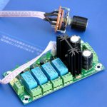
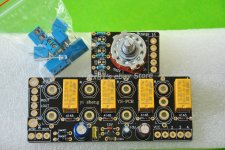
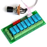
Whilst It's nice to design my own input selector, it's a rather mechanical process of layout space for some relays.
I'm having doubts that it's worth the trouble after seeing some ready made stuff available on ePay. There's a balanced input option which I could use to switch the signal and the signal ground lines. All I have to do is hit 'buy now' and the darn thing will turn up ready to be bolted into the chassis. This is really tempting.
Attachments
Will you switch ground also ( only needs one ground )? Make before brake time constants using NE555 if space allows? I have used fancier solutions and always came back to them. You can serial connect them which seems better than the NE555 data sheet. If so a transistor every so often to account for voltage losses. 12V relays work OK at 13 to 9 VDC. In this use the open collector transistor used for repating waveforms can be commoned to reduce losses and raise current output ( circa 350 mA ). Use high senstivity relays to keep load minimal.
Member
Joined 2009
Paid Member
The balanced options provides a means to switch two signal lines per channel so this would seem to be the way to go if I want to switch grounds. Some engineering may be needed on the timing aspect but is probably doable one way or another. I'd have to take a careful look, these Chinese boards are not always what they seem and could end up costing more effort than it saves.
Last edited:
Release time is usually faster than operate time in relays. One option to create make-before-break is to use them in reverse - all on, and use the NC contact to do the desired input connection.
Last edited:
That's not bad. On my system although built for pennies the switched grounds make it one of the better ones compared with ones that's friends have. My speakers are 99 db/watt so really show it. Mixed ground noise must be a very high distortion factor if people are excited about - 90 dB distortion. Hum and RFI are distortions. I don't mind having what my sources have, I don't want what isn't them.
Member
Joined 2009
Paid Member
what about rapid mute of output when doing source switching, would this make it worse or potentially better ?
what about rapid mute of output when doing source switching, would this make it worse or potentially better ?
I do it even in the R-2R attenuator to remove the "artifact" when relay configuration switches from 010000 to 011111 and back when changing the volume. Doing so I do not hear any artifacts since it is so fast that I can't notice (Omron G6K relays which I use have 3ms ON and OFF delay). One thing to watch out for is zero DC on signal lines, otherwise the change in DC bias will produce a noticeable "plop".
Regards,
Oleg
Member
Joined 2009
Paid Member
... I do not hear any artifacts since it is so fast that I can't notice ... watch out for is zero DC on signal lines, otherwise the change in DC bias will produce a noticeable "plop".
Thanks for that Oleg as this gives me more confidence in this approach.
I assume that the 'safest' approach from a dc-perspective is to have a capacitor in the signal line ? (even though people are allergic to them)
Capacitor will do it, just don't forget to reference its "open" end to GND using 1~2 MOhm resistor to prevent charging when it is disconnected.
How about avoiding the caps but put the 1M-ohm bleeders on each input anyway, continually connected to each input, to drain any dc on the source device's caps?
Exactly this is what I've done on my input selector PCBs. This way even if the input is not selected it is still referenced to the proper GND potential. I would anyways fit the capacitor between the input selector and active gain stage. One can never be sure if the output of what's going into the input selector is DC or AC coupled.
Member
Joined 2009
Paid Member
I will have a capacitor on the input to the gain stage - it's almost mandatory because it's a Singleton input design.
I was thinking that instead of placing the gain stage after the volume pot, I should place it beforehand as it avoids amplifying the noise of the volume pot. I read about this from D. Self. Of course, I will ensure that my Source components have low enough output impedance to drive the volume pot.
I was thinking that instead of placing the gain stage after the volume pot, I should place it beforehand as it avoids amplifying the noise of the volume pot. I read about this from D. Self. Of course, I will ensure that my Source components have low enough output impedance to drive the volume pot.
the source should have it's own megohm leakage resistor so that when disconnected charge does not build up on the source output pin.How about avoiding the caps but put the 1M-ohm bleeders on each input anyway, continually connected to each input, to drain any dc on the source device's caps?
If omitted then charge will build up and connecting to a DC blocked power amplifier could send a pulse through the power amplifier that can blow the speaker.
Fitting the leakage resistor to the Receiver instead of the Source does not prevent that catastrophe.
I will have a capacitor on the input to the gain stage - it's almost mandatory because it's a Singleton input design.
I was thinking that instead of placing the gain stage after the volume pot, I should place it beforehand as it avoids amplifying the noise of the volume pot. I read about this from D. Self. Of course, I will ensure that my Source components have low enough output impedance to drive the volume pot.
Placing an active stage before the vol pot limits the overload margin. In extreme cases you can have unavoidable distortion and/or clipping of the input signal. And turning down the vol pot does not remove that distortion/clipping.
Bleed resistors everywhere! Why not.
Inputs...switches...volume...gain stage...buffer
Phono as another input that happens to be in the same box
On second thoughts, it depends what gain your gain stage has. If it's just 2x or so then no problem putting it before the buffer...then you don't have to think about your gain stage input impedance creating a variable LPF with the volume pot. I think I would do it this way if I were using a low gain and a nice IC buffer (nudge).
What are you going to use for a volume control?
Last edited:
Member
Joined 2009
Paid Member
D. Self also talked about overload. He then went on to suggest putting some gain before the vol. pot and some gain afterwards. This approach is a bit like the chicken in the middle of the road doesn't know whether to keep going to the other side or retreat to the starting point.
As the gain stage should be switched in/out from the front panel it should only be in operation on weak signals so overload is quite avoidable. I expect to use the gain stage rarely, if at all, with my sources and amplifiers. But it's nice to have one just in case and it allows me to 'hear' what a gain stage can do.
Agree - no reason to be stingy on bleed resistors 😀
Haven't picked a vol. pot yet. I don't think I will get along with a stepped attenuator because of the finite control steps - unless I were to get one of those 48 position ones from Khozmo (their stuff looks pretty but it looks like break-before-make which isn't good). That leaves me considering PEC, Alpha and TDK as brand names that people have said good things about.
I do like the idea of the LDR attenuator, but it is known to produce measurable distortion on strong signals and although there are folk who like it subjectively so perhaps it's one of those things you have to try for yourself ?
Last edited:
TKD are pricey. ALPs aren't bad.
I don't know what the characteristics are of photo-resistors other than they are made of silicon. The last time I used one was when I was 12 and had one of those electronics experiment boards with the springs. My favourites were the photo-cell and the meter.
I generally don't rate silicon. I spend almost all of my audio design time trying to compensate for its woes. Silicon doesn't make good capacitors and probably doesn't make great resistors either.
Member
Joined 2009
Paid Member
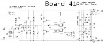
Board#1 - the Phono Stage
I was finding the layout cramped and not to my liking. So I took a step back and am now exploring a suggestion made earlier in the thread to focus on the phono stage. By making the first board the phono module there is more space to layout the circuit.
In fact, it looks as if this first board would be suitable as the main meal in a stand-alone phono amplifier, without being part of a more complex pre-amp. If anybody fancied building a dual-mono phono-amp then this would be a good place to start. I rather like that.
Attachments
Last edited:
- Status
- Not open for further replies.
- Home
- Source & Line
- Analog Line Level
- TGMC - a modular control pre-amplifier