I checked the whole thread but I couldn't found any layout pdf or gerber files.
Is this files shared or am I being delusional?
Is this files shared or am I being delusional?
The speakers I'm planning to use (Statement II) are specified by the builder to need a minimum of 100W@8Ω. The speaker itself is nominally 4Ω though.
Would this amplifier be able to satisfy that?
The page for the original P3A specifies:
Power (42V supplies, 8 ohm load) 90W
Power (35V supplies, 8 ohm load) 60W
Power (35V supplies, 4 ohm load) 100W
The 90W with a 42V supply seems close enough, I'm not aiming to do concert levels here. How close is this number to the TGM8?
The P3A page also states "Operation into 4 ohm loads is not recommended with the 42V supplies."
Is this still applicable to this amplifier or have it gone through enough changes that it would be able to handle it?
I'd be using parts from the BOM in post #950 if it would help, which lists that the values are for supplies < +/- 50V.
I recall adding add’l final output transistors can mitigate that because they share the current. BUT don’t trust me. Can’t recall if the PCB allows multiple transistor.The speakers I'm planning to use (Statement II) are specified by the builder to need a minimum of 100W@8Ω. The speaker itself is nominally 4Ω though.
Would this amplifier be able to satisfy that?
The page for the original P3A specifies:
Power (42V supplies, 8 ohm load) 90W
Power (35V supplies, 8 ohm load) 60W
Power (35V supplies, 4 ohm load) 100W
The 90W with a 42V supply seems close enough, I'm not aiming to do concert levels here. How close is this number to the TGM8?
The P3A page also states "Operation into 4 ohm loads is not recommended with the 42V supplies."
Is this still applicable to this amplifier or have it gone through enough changes that it would be able to handle it?
I'd be using parts from the BOM in post #950 if it would help, which lists that the values are for supplies < +/- 50V.
I love smd and through hole.I forgot to mention another key thing about the input stage. By controlling the d.c. level in the feedback network in this way, the feedback capacitor is quickly brought up to the correct bias voltage and doesn't create the turn-on issues normally associated with a Singleton input. There are other contributions to the turn-on behaviour of the P3a and this is something I still have to look at.
PCB ? --- I'm afraid my recent designs have been unpopular around here because I make use of a mixture of through-hole and surface mount. Some people really are still afraid, in this day, of surface mount. My plan so far on my TGM7 has worked fairly well. I use through hole for parts with 3 or more connections such as transistors and trim-pots. I use through hole parts for all large capacitors too. Where I have been using surface mount is for resistors and even then I use 1206 sized parts. These are parts are big enough to read their labels so you can read off the values of them. Have a look at the attached photo to see a through hole resistor lying on top of a pcb near a surface mount resistor. It's not hard to use at all, a pair of small pliers to hold it in place whilst you solder one end at a time. You end up being able to solder them in quickly and easily, with little solder. They allow for shorter signal traces and more compact design which can be very handy when your feedback amplifier has open loop unity gain in the MHz region. The only disadvantage is that you can't easily remove surface mount resistors unless you have two soldering irons, or be prepared to crack it and remove it in two pieces. I haven't decided which approach to designing the pcb to take with TGM8 yet.

Member
Joined 2009
Paid Member
There’s no issue driving 4R speaker loads with this amplifier, the MOSFET‘s can handle the current.The speakers I'm planning to use (Statement II) are specified by the builder to need a minimum of 100W@8Ω. The speaker itself is nominally 4Ω though.
Would this amplifier be able to satisfy that?
The page for the original P3A specifies:
Power (42V supplies, 8 ohm load) 90W
Power (35V supplies, 8 ohm load) 60W
Power (35V supplies, 4 ohm load) 100W
The 90W with a 42V supply seems close enough, I'm not aiming to do concert levels here. How close is this number to the TGM8?
The P3A page also states "Operation into 4 ohm loads is not recommended with the 42V supplies."
Is this still applicable to this amplifier or have it gone through enough changes that it would be able to handle it?
I'd be using parts from the BOM in post #950 if it would help, which lists that the values are for supplies < +/- 50V.
It has occured to me that it would be possible to add parallel MOSFETs and increase the design margin to allow for even higher powers.
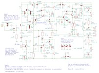
Hi, I built a Naim clone and thought I want to try something different, so I read through this impressive thread. I used the Kicad files posted earlier to add some small updates, please see attached screen shot. The diodes on the drivers are removed as @Bigun suggested and the protection circuit is updated as discussed in the TGM10 thread. Please let me know if I got it right!
Attachments
Member
Joined 2009
Paid Member
Just a quick look - don't see any issues. It's been awhile since I looked at this design but I can tell you that this amp is still in use as my main SS amplifier. As it's been awhile I would check carefully on parts availability. There are not likely to be any issues as there are good (or possibly better) alternatives to all the parts I've used. In fact, you should avoid going to any extreme lengths to obtain the specific parts I've used as I don't consider these specific choices to be crucial for the performance and sound quality. Of course they have to be equivalent.
I do find that a careful-hand is required to set the dc-offset. If I were to re-design I might try to improve this situation. One obvious option is to add resistors in series with the potentiometer so that you can reduce the value of the potentiometer (maintaining the same total series resistance) so that it's less sensitive to the rotation angle of the adjustment.
You might hopefully improve on my pcb layout so that it's easier to assemble - there are a lot of parts and it was dense. Of course, short path lengths are needed in some areas (e.g. the RC snubbers on the power FETs).
Great timing JPK! I've been sitting on four tgm8 boards for some years and only this week have revisited the entire thread (I'm nearly at the end) and I have started to accumulate the required parts. I may be able to incorporate some of your ideas once I absorb your revisions.
Please share your pcb pdf sirJust a quick look - don't see any issues. It's been awhile since I looked at this design but I can tell you that this amp is still in use as my main SS amplifier. As it's been awhile I would check carefully on parts availability. There are not likely to be any issues as there are good (or possibly better) alternatives to all the parts I've used. In fact, you should avoid going to any extreme lengths to obtain the specific parts I've used as I don't consider these specific choices to be crucial for the performance and sound quality. Of course they have to be equivalent.
I do find that a careful-hand is required to set the dc-offset. If I were to re-design I might try to improve this situation. One obvious option is to add resistors in series with the potentiometer so that you can reduce the value of the potentiometer (maintaining the same total series resistance) so that it's less sensitive to the rotation angle of the adjustment.
You might hopefully improve on my pcb layout so that it's easier to assemble - there are a lot of parts and it was dense. Of course, short path lengths are needed in some areas (e.g. the RC snubbers on the power FETs).
Member
Joined 2009
Paid Member
Read first post, it has a contents list. If everything is working, you can download files etc. This includes Gerber files which you can use to order PCB’s without ever having to learn the layout software.
I no longer design pcb’s using that software and I will use KiCad in the future. However, I’ve yet to learn the interface for KiCad so I’m not going to be able to offer assistance on layout.
I no longer design pcb’s using that software and I will use KiCad in the future. However, I’ve yet to learn the interface for KiCad so I’m not going to be able to offer assistance on layout.
Ok, I will walk through the BOM and post the final KiCAD files later on.
@Bigun, what voltage rating does the speed cap for the protection circuit need?
Regarding alternatives to the semi conductors: I vagely remember somebody mentioned MJE340/350 (or was it MJE243/253?) as drivers and MJL4281/4302 as power devices - or was that in the TGM10 thread? BTW the specced drivers and output devices are listed in stock at mouser...
Last edited:
Member
Joined 2009
Paid Member
I’d want to run a Spice Sim as the lazy way to figure out voltage rating for that cap but off the top of my head, the end near the output could presumably swing + / - the full rail voltage (i.e. twice that of one rail) under a worse case fault condition but by then your priority isn’t the life expectancy of the cap! In normal operation it’ll never experience d.c. at the full (single) rail voltage so if you rate it close to the rail voltage you’ll have some headroom. e.g. for +/- 42V rails then 50V is more than plenty and 35V likely OK. A quick look at Digikey and there are lots of 50V 1uF electrolytic, through hole 5mm dia caps for less than 50c.
Last edited:
e.g. for +/- 42V rails then 50V is more than plenty and 35V likely OK. A quick look at Digikey and there are lots of 50V 1uF electrolytic, through hole 5mm dia caps for less than 50c.
Thanks for clarification! I will have a spare +12V rail in my amp and might want to use that for the protection circuit - would that affect part values / ratings?
Member
Joined 2009
Paid Member
Would you be so kind and help me figure out the values? I guess I need to reduce R36, R38-41 and D5...?
Member
Joined 2009
Paid Member
Not easy right now due to busy with the day job, but I'd encourage you to understand more about how the circuit works as then you'll be able to do it yourself. Off the top of my head, referring to the schematic in post #1,169 -
Let's talk about the Zener diode first. It is there to provide a reference voltage to the base of Q17 that is a few volts below the power rail. When you turn off the power and the power rail collapses the voltage on the emitter of Q17 will eventually (it happens fairly quickly) fall below this reference voltage at the base and the p-type emitter-base junction will no longer be forward biassed so the transistor turns off - which stops current flowing through the solid state relay and hence disconnects the output from the amplifier. We want this to happen in order to avoid any audible noises or sub-sonic excursions of your speaker woofers when the amplifier powers down. So first off you can see that you'd need to reduce the Zener D5 voltage to around 12V - 7V = 5V. It doesn't have to be exact, the idea is to catch the supply rail falling.
But note: If you power this circuit from a separate 12V supply which doesn't collapse at the same time and rate as the main amplifier supply rail, the circuit may not turn off the amplifier output soon enough to prevent shut-down noises. That will depend on your power supply implementation and to keep it simply why not just follow the circuit as I've published and forget the 12V supply ??
- Home
- Amplifiers
- Solid State
- TGM8 - my best amplifier, incredible bass, clear highs, no fatigue (inspired by Rod Elliot P3a)