Member
Joined 2009
Paid Member
Try it the other way around. Buffer first, VAS 2nd. Then you will find that you've unloaded the LTP from driving Cdom. It might be counter-intuitive to put the buffer first but I think it provides some interesting benefits.
Member
Joined 2009
Paid Member
nope - haven't tried it. It's just theory (simulation) but it looked interesting 🙂
What you will find is that the compensation cap goes on the VAS (2nd device), whereas you need only a very small compensation cap on the first device to ensure stability of the LTP-VAS.
So, if you put the comp. cap on the 2nd device it's now actively driven from both ends. The emitter of the 1st device and the collector of the 2nd device. Slew rate is now more symmetrical and no longer limited by the current output from the LTP.
Will I build it -- well it's in the queue along with a few other things 😀
Member
Joined 2009
Paid Member
I like to use the free LTspice tool to simulate circuits and understand at least in principle how they might behave. Have you tried this ?
The RC input filter - not sure if you need it, what are you trying to filter ? - do you expect to operate in a noisy RF environment ?
The Miller cap is almost always needed to make an amplifier of this topology stable. I would doubt you can eliminate it without some other equivalent compensation method. The miller cap is controversial, some hate it, some don't. My own listening tests tell me that it has an optimum value.
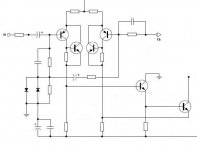
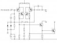
Actually this amp is highly mature and uses several stabilising techniques, most simply preventing excessive slew and thus inhibiting oscillation. It also has a very small output inductor, with split feedback before and after presumably to promote stability into capacitive loads.
1. C508 across the bases of the long tailed pair.
2. C517 across the feedback resistor, R536, reducing gain with frequency.
3. C519 in series with R540 across collector load of Q507.
4. C529 and C526 shunting VAS output to AC ground.
Certainly there is no formal lag compensation across the VAS collector/base, but the foregoing demonstrate that stability has been very carefully configured regardless.
Hugh
Member
Joined 2009
Paid Member
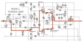
Your circuit looks familiar... 25W Class-A Power Amplifier
Well, two newbies isn't the best approach here (meaning you and I) - it perhaps deserves a new thread where you can attract some help from people like Hugh. I am happy to chime in with my thoughts but the TGM amplifier is my only project so far 🙂
Well, two newbies isn't the best approach here (meaning you and I) - it perhaps deserves a new thread where you can attract some help from people like Hugh. I am happy to chime in with my thoughts but the TGM amplifier is my only project so far 🙂
Member
Joined 2009
Paid Member
no issues at my side, you're discussion was welcome in this thread, I but I'm a bit nervous about you relying on my advice without more input from others 😱
I think the CFP Vbe multiplier is interesting... Many would say it is unnecessary, I wonder what the sonic impacts are? (EDIT: it is probably there to increase the gain that's lost through the LED).
Some possible improvements:
1: NPN VAS, with better transistors (but, we would have to use a PNP VAS...). Generally NPNs have higher gain.
- keantoken
Some possible improvements:
1: NPN VAS, with better transistors (but, we would have to use a PNP VAS...). Generally NPNs have higher gain.
- keantoken
Last edited:
Member
Joined 2009
Paid Member
UPDATE:
Well it was time to bring back all the parts I had built for a reunion. This weekend I was able to find all the pieces. I need to get back to the bench and do some DIY again.
I was not happy with the mess that I found. I stripped away a lot of things, removed a lot of wiring and cut it all back like an overgrown garden. What on earth was I thinking when I built this monster.
I took out the inductors from the psu as they were creating a problem with solid mounting of the pcb and replaced them with 0R33 resistors. The inductors weren't that big at 330uH and so I'm not expecting any degradation in sound. The psu is now simply a set of soft-recovery diodes for the rectifier followed by CRC. The first C remains 14mF per rail (plus film bypass), the second C remains 18.8mF per rail (plus film bypass).
Volume control removed - too messy. Will have to re-develop. ipod as source.
I set it back up with one channel of TGM1 and one of TGM2. Biass was wrong on both of them. I'd been operating them a bit warm, over 100mV across the output emitter resistors. Trimmed both back to 58mV.
And I did the classic. My probe tip slipped on TGM2 and shorted the Collector-Emitter of the output device. Nice blue coloured flash ! It still worked, but at higher volumes it produced a lot of crackling interference. I guess putting the +ve rail to the emitter reversed biassed the b-e junction - not good. I'll replace the device tomorow.
How do the amplifiers sound ?
Not as good as I remember - the passage of time has made me more honest. But I could sense the same magic potential and I will be making a couple of adjustments to fix this up pronto.
TGM1 - needs more current through the LTP, it's running too lean. And compensation is too heavy, OLG falling off too early. A resistor and capacitor will fix this.
TGM2 - not sure yet, probably just needs a new output device but phase lead is too heavy and needs to be cut back. And I will be trying out some ideas to sweeten the sound as I remember that TGM1 always was a little more musical than TGM2 but couldn't match it for bass and clarity.
Member
Joined 2009
Paid Member
Upgrades completed !
TGM1 - increased the current through the LTP by reducing the feed resistor from 15k to 10k, reduced phase lead from 22p to around 5p and reduced LTP collector load resistor to minimize the dc offset at the amplifier output. The 'special' resistor used to bleed some of the output to the top of the LTP was replaced with a lower value (to compensate for the fact that LTP current was increased). Sounds good !
TGM2 - Tried reducing LTP emitter degeneration from 33R to 15R. Theoretically this improves the OLG so that it's higher than TGM1. But the sound was not as nice so I put it back to 33R. Sounds clearer with better bass than TGM1. But not as musical. This was also solved with some adjustments and now it sounds better all round compared with TGM1.
Next step is to rebuild the chasis and decide what to do with the volume control.
Output Capacitor: just for interest, and although not needed, I thought I'd listen to the amplifier through an output capacitor. I found that the bass was noticeably worse off through a 220uF Nichicon MUSE. But through a 2,200uF Nichicon MUSE the bass was fine. I also tried a 10,000uF Nichicon HE cap. Overall I was hard pressed to hear a difference between the use of the two larger capacitors but I could hear a very subtle difference between cap and no cap. The output without a capacitor seemed to have just a tad more 'space' around the upper mids. That's about all I know how to explain what I heard. I concluded that I could be happy with an amplifier that used an output cap.
I tested quite a few capacitors with my signal generator, and found that for higher values, say over 1000uF, there was always resonance right in the middle of the audio spectrum, at say 3KHz, sometimes 4KHz (the larger the capacitor, the lower frequency the resonance). So you seem to be right about something going on in the mids.
- keantoken
- keantoken
These degeneration resistances in the long tail produces huge difference
in measurements and in sonics too.
this is a great trick for "tuning" the amplifier...i am glad you've got it, you discovered that too.
I think you have enormous value... and you were detected by Hugh Dean as someone has value..he was right, he is good to evaluate people.
Yes..increasing condenser the bass turns better..but removes focus in other frequencies too as you should have perceived..we increase bass and we make sabotage in the midranges.
Good!
regards,
Carlos
Last edited:
Member
Joined 2009
Paid Member
Thanks for the good words Carlos, you guys set a high standard to try and follow 🙂
I am trying to understand why the degen matters so much and I can only conclude that it helps compensate for device mismatches. But in a quick simulation I saw that the higher degeneration reduces the 5th harmonic so perhaps there is more going on.
But what are we to do with single supply rails then, if capacitors are bad. I have some single rail transformers that should not go to waste and I thought some TGM variation with a Singleton front end might be the path to take.
Is there opinion on whether it's best to
a) use a capacitor and suffer the consequences ?
c) use a bridged amplifier to eliminate the capacitor ?
d) use a virtual earth ? (which is similar to option c) when you think about it)
and why do we hear these differences when even a dual rail amplifier sends the signal through the power supply rail capacitors anyway ?
Member
Joined 2009
Paid Member
regards,
Carlos
Ok !
... just one big one, a big one plus film bypass, or many small ones ?
Another channel of TGM2 was finished today. Started a long time ago. The old TGM1 channels are rejected. Removed. I don't know if it was me being too lazy to match the LTP devices on TGM1, or that I have improved TGM2 sufficiently, but the TGM2 just sounds that much better I can't listen to TGM1 any longer. TGM1 is fired, no longer desired or recommended. TGM2 is stronger and more musical.
- Status
- Not open for further replies.
- Home
- Amplifiers
- Solid State
- TGM2 amplifier