Member
Joined 2009
Paid Member
Sounds like good advice.
I'd better put it on a new thread - TGM3....
http://www.diyaudio.com/forums/solid-state/167369-designing-tgm3-output-triples.html
(and I'll have to upgrade the output cap !)
I'd better put it on a new thread - TGM3....
http://www.diyaudio.com/forums/solid-state/167369-designing-tgm3-output-triples.html
(and I'll have to upgrade the output cap !)
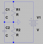
My suggestion, if your transformer doesn't have a center tap, is to use a simple resistor virtual ground. Have the resistors pass enough current to give your amp the DC it has to pull from ground. These resistors will also set the maximum DC offset current through the speaker, since too much offset will elevate ground to clipping.
This way there is DC protection for the speaker and what else is connected to it. This very simple virtual ground is so blameless I'm not sure why I haven't seen it used more. I could understand using it in commercial amps to simplify speaker protection.
Looking back through this thread, it is odd to think my earlier posts were only less than a year ago. I posted those at a time when I had just realized I had developed some competency in electronics using the simulator. I kinda feel like post #55 was a moment in history. In my history at least, in the fishbowl of my mind.
- keantoken
Attachments
Member
Joined 2009
Paid Member
I did build a virtual earth circuit like that in my BotchUp thread (which is where the transformers are) and it seemed to work, but as far as I can tell it just moves the output capacitor from one side of the speaker over to the other side of the speaker !?
Looking back at my old posts reminds me of how little I knew when I start in this hobby. I feel like I came a long way in a year even though I've not built enough to earn my stripes yet. You have certainly learned a lot, more than I have and more than I have to time to do...
Looking back at my old posts reminds me of how little I knew when I start in this hobby. I feel like I came a long way in a year even though I've not built enough to earn my stripes yet. You have certainly learned a lot, more than I have and more than I have to time to do...
Well I wonder about myself sometimes now, I suspect I've reached that terrible age of neural pruning...
The difference is that Ground is now between the speaker and capacitor. This ground is also connected to input ground. This allows the amplifier to correct for the capacitors, since any capacitor distortions show up on input AND power ground, which cancels out the effect on the speaker. The amp only cares about the voltage difference between ground and speaker, and we have eliminate the capacitor from this.
I hope my explanation is clear.
- keantoken
Member
Joined 2009
Paid Member
OK - so Keantoken and I have taken our chat on capacitors and related stuff to continue in a separate thread:
http://www.diyaudio.com/forums/solid-state/167369-designing-tgm3-output-triples.html#post2196587
this current thread is for TGM2.
http://www.diyaudio.com/forums/solid-state/167369-designing-tgm3-output-triples.html#post2196587
this current thread is for TGM2.
My suggestion, if your transformer doesn't have a center tap, is to use a simple resistor virtual ground. Have the resistors pass enough current to give your amp the DC it has to pull from ground. These resistors will also set the maximum DC offset current through the speaker, since too much offset will elevate ground to clipping.
This way there is DC protection for the speaker and what else is connected to it. This very simple virtual ground is so blameless I'm not sure why I haven't seen it used more. I could understand using it in commercial amps to simplify speaker protection.
Looking back through this thread, it is odd to think my earlier posts were only less than a year ago. I posted those at a time when I had just realized I had developed some competency in electronics using the simulator. I kinda feel like post #55 was a moment in history. In my history at least, in the fishbowl of my mind.
- keantoken
I have been using this kind of "virtual ground" since the seventies, modding several single supply commercial amplifiers.
I used to feel an improvement in sound quality.
Though the caps values have to be doubled to keep the same filtering.
Member
Joined 2009
Paid Member
Member
Joined 2009
Paid Member
Member
Joined 2009
Paid Member
And the last step is to add to the clean sound of the amp by introducing a small bit of 'tubeiness' http://www.diyaudio.com/forums/solid-state/168503-tgm-amp-goes-tubey.html#post2214871
In putting the lid on the amp I found that the margin of safety on the lead compensation was too small and increased it slightly.
In putting the lid on the amp I found that the margin of safety on the lead compensation was too small and increased it slightly.
Member
Joined 2009
Paid Member
Well this maybe the last chapter for TGM2. I did a direct comparison between the TGM2 amplifier and my CELLINI amplifier using a pair of APOLLO open baffle speakers. I employed the additional tweaks on TGM2 to inject a little even harmonics which helped on the top end to smooth things further.
At first I thought the tube amp couldn't match TGM2 for bass, and I put it down to the lower damping factor of a no feedback tube amp. But I went back through the same music using the Tube amp and I was mistaken - the bass was no different, it was the particular recording.
The tube amp was simply better in all respects compared with TGM2. Despite the lower power rating of the tube amp it was plenty powerful enough in my largish basement. The music played through the tube amp was clearer all across the range, it sounded less distorted to my ears, no fatigue, clear and open. TGM2 sounded harsh in comparison.
for Cellini: http://www.diyaudio.com/forums/tubes-valves/167872-my-cellini-triode-amp.html
for Apollo:http://www.diyaudio.com/forums/full-range/174632-apollo-ob.html
Member
Joined 2009
Paid Member
I thought it was time to revisit an old friend. I went back to look at this amplifier since it's been in active service now for awhile. I was wondering if there was anything I might want to do to tweak it for improved performance. I still marvel at the Sziklai topology, in this case used in the LTP.
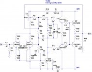
I have looked at two simple changes
a) reduce the output device emitter resistor values by paralleling a pair of lower valued resistors to get an effective Re = 0.2 Ohm.
b) add an EF buffer to the VAS to provide more drive into Cdom. In this arrangement Cdom is driven from both ends. Note that this differs from others (e.g. DX Blame) in that Cdom is not wrapped around the two device VAS, it is isolated from the LTP altogether. The buffer is also before the VAS not afterwards. I first alluded to this idea over a year ago (see post 101).
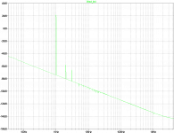
The attached is a schematic and simulated FFT. I'm quite pleased with the results of these changes, a little more H2 & H3 than the baseline design and a lot less higher order harmonics. This may be worth getting out the soldering iron...
I'm calling this TGM2X.
I have looked at two simple changes
a) reduce the output device emitter resistor values by paralleling a pair of lower valued resistors to get an effective Re = 0.2 Ohm.
b) add an EF buffer to the VAS to provide more drive into Cdom. In this arrangement Cdom is driven from both ends. Note that this differs from others (e.g. DX Blame) in that Cdom is not wrapped around the two device VAS, it is isolated from the LTP altogether. The buffer is also before the VAS not afterwards. I first alluded to this idea over a year ago (see post 101).
The attached is a schematic and simulated FFT. I'm quite pleased with the results of these changes, a little more H2 & H3 than the baseline design and a lot less higher order harmonics. This may be worth getting out the soldering iron...
I'm calling this TGM2X.
Attachments
I'm calling this TGM2X.
I recommend bootstrap instead of active CS, for better 'sonics'. Then you could call it TGM2-EX
😀
Oh shoot! You already have that! Hmmm, I'd still call it the TGM2-EX.
Last edited:
Member
Joined 2009
Paid Member
with OS's AX and BX the addition of an EX would have DX surrounded, there might have to be a merger. Better I stick with just the X.
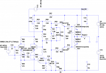
That 820 resistance in first VAS is an attempt to limit current to the 2N5550
But if someone make a mistake (they did in Brazil) to inject 6 volts of square waves... with 1K, or 820 ohms, the poor devil, the small transistor will die anyway.... so, my dear friend Bigun, this is a solution that does not fix the weekness of this stage.
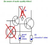
The inclusion of protection, these hell transistor that "feels" current in the second VAS emitter and drains excesses of input current that may "hurt" the first VAS... draining it to the negative rail ... will kill dinamics...will sound very poor at peaks. (image attached)
The reduction of current in the first VAS turns the sound awfull, measure and you will see the strange currents and VBEs you will have.... the solution is 100 ohms or 220 ohms, tuned listening... despite this turns the stage very weak to face abuse.
Despite people know the input is for 750 milivolts RMS (mine ones are this way...my standard.... almost the same old fashion 1 V standard)... we have people using crazy preamplifiers with 10 volts output....so...you will need power amplifier with voltage gain 2 to work with them.... strange decisions that i would never understand what is going on inside these guys brains...well... two guys did...one because an accident..he took a generator with the output knob turned all the way up...having several volts (6) and with square wave output.. and he plugged into the poor devil amplifier....of course overdriven the stage... too much current resulted from colector to emitter and the poor devil gone...the transistor, of course, burned....bad use....also can be burned if we connect it under watter..inside a swiming pool for instance.
You see that when you protect the amplifier against such kind of thing, you will be producing amplifier to "this kind of crazyness"..so... will be making it to 1 or 2 guys that does such kind of thing and allowing deep sacrifices in sonics that will be bad to everyone that gonna use your amplifier... you should make amplifier to the regular people and not to exceptional people.
The Troyan they gonna use in my last Brazilian group buy and last developed project as amateur and DIY, have MJE15032 as first and second VAS.... this one these exotic guys cannot burn.
If we go protecting too much..we go killing sonics.... result alike LM chips...overprotected and only plays good music at power peaks or 20 watts..if you try more, then you engage all the hell killer protections..dinamics is killed, audio quality disappear, tone ballance finishes..you go increasing volume and only treble will go increasing.... high power to these chips results awfull...they protected their ICs and let your good musical taste and ears unprotected..... they found solution to their own design problems and physical limits on their devices ...and you..the one will listen..well.... well... well...... your problem!
The neurosis about to go protecting, or overprotecting something that can be damaged during some apocalyptic event, may result that people will be
enclosing their amplifiers in titanium, 5 inches thick sealed case..because we can have a Catterpillar trying to smash the amplifier... or an alien or terrorist attack..or a Meteor falling in earth.... also a Nuclear bomb.... such kind of exageration.... will be killing sonics in the name of extreme reliability... crazyness.... a perfectionist obsession.... these guys will produce a 120 kilos bicicle... an undestructable sport bicicle..sadly will last long but will not run fast..and if you have muscles to drive it to run fast..will be awfull to stop.... this is the analogy...to overprotect is the to produce a solid heavy duty race bicicle...make to everything but to run.
820 ohms will not protect against bad use anyway...but you will be loosing in sonics.... make a test and observe the difference in sonics.... there are some guys saying you should install 2 K in the colector...well... this may protect..but keep the amplifier switched off..as the sonics will be untollerable.
This is my cooperation dedicated to a nice guy... a hug to you Bigun.
regards,
Carlos
But if someone make a mistake (they did in Brazil) to inject 6 volts of square waves... with 1K, or 820 ohms, the poor devil, the small transistor will die anyway.... so, my dear friend Bigun, this is a solution that does not fix the weekness of this stage.
The inclusion of protection, these hell transistor that "feels" current in the second VAS emitter and drains excesses of input current that may "hurt" the first VAS... draining it to the negative rail ... will kill dinamics...will sound very poor at peaks. (image attached)
The reduction of current in the first VAS turns the sound awfull, measure and you will see the strange currents and VBEs you will have.... the solution is 100 ohms or 220 ohms, tuned listening... despite this turns the stage very weak to face abuse.
Despite people know the input is for 750 milivolts RMS (mine ones are this way...my standard.... almost the same old fashion 1 V standard)... we have people using crazy preamplifiers with 10 volts output....so...you will need power amplifier with voltage gain 2 to work with them.... strange decisions that i would never understand what is going on inside these guys brains...well... two guys did...one because an accident..he took a generator with the output knob turned all the way up...having several volts (6) and with square wave output.. and he plugged into the poor devil amplifier....of course overdriven the stage... too much current resulted from colector to emitter and the poor devil gone...the transistor, of course, burned....bad use....also can be burned if we connect it under watter..inside a swiming pool for instance.
You see that when you protect the amplifier against such kind of thing, you will be producing amplifier to "this kind of crazyness"..so... will be making it to 1 or 2 guys that does such kind of thing and allowing deep sacrifices in sonics that will be bad to everyone that gonna use your amplifier... you should make amplifier to the regular people and not to exceptional people.
The Troyan they gonna use in my last Brazilian group buy and last developed project as amateur and DIY, have MJE15032 as first and second VAS.... this one these exotic guys cannot burn.
If we go protecting too much..we go killing sonics.... result alike LM chips...overprotected and only plays good music at power peaks or 20 watts..if you try more, then you engage all the hell killer protections..dinamics is killed, audio quality disappear, tone ballance finishes..you go increasing volume and only treble will go increasing.... high power to these chips results awfull...they protected their ICs and let your good musical taste and ears unprotected..... they found solution to their own design problems and physical limits on their devices ...and you..the one will listen..well.... well... well...... your problem!
The neurosis about to go protecting, or overprotecting something that can be damaged during some apocalyptic event, may result that people will be
enclosing their amplifiers in titanium, 5 inches thick sealed case..because we can have a Catterpillar trying to smash the amplifier... or an alien or terrorist attack..or a Meteor falling in earth.... also a Nuclear bomb.... such kind of exageration.... will be killing sonics in the name of extreme reliability... crazyness.... a perfectionist obsession.... these guys will produce a 120 kilos bicicle... an undestructable sport bicicle..sadly will last long but will not run fast..and if you have muscles to drive it to run fast..will be awfull to stop.... this is the analogy...to overprotect is the to produce a solid heavy duty race bicicle...make to everything but to run.
820 ohms will not protect against bad use anyway...but you will be loosing in sonics.... make a test and observe the difference in sonics.... there are some guys saying you should install 2 K in the colector...well... this may protect..but keep the amplifier switched off..as the sonics will be untollerable.
This is my cooperation dedicated to a nice guy... a hug to you Bigun.
regards,
Carlos
Attachments
Last edited:
Bigun, the stability characteristics depend on the loading of the LTP at HF. The reason Miller compensation works is because it loads the LTP at HF, lowering gain to the point where the amplifier is stable. If the amp is still stable with a buffered Cdom, then maybe you didn't need so much compensation in the first place.
Also, is you loopgain probe placed correctly? Shouldn't it be placed right after the OPS?
On the other hand, every amp is different, and some commercial designs have less compensation then they are "supposed to". I have been looking at different compensation schemes a lot, do you think you could post an OLG plot so I can have a gander? I think I could say how viable the idea is (not that I can act as a substitute for building it).
Also ask OStripper about TMC compensation. He has been using it in his designs with success, and it eliminates a lot of crossover/OPS distortion.
- keantoken
Member
Joined 2009
Paid Member
Carlos,
Thank you for rescuing me from this folly - your experience shines through again. I did a quick check in Spice with a large input signal. The amplifier clips of course, and that extra transistor becomes a bright star for a brief time and then lets out all of the smoke. So I must either put in a larger device that may survive more abuse (e.g. BD139), or I will choose not to include this addition to the design.
Kean,
I have to fess up and point out that I've increased LTP degeneration (see my schematic posted above) which confers additional stability to the LTP and is responsible for a bit more H2/H3 in the FFT - something I was looking to achieve.
I'll post the files shortly in case you fancy a gander at the OLG.
I'm not considering TMC at this point, I believe it offers more with high OLG designs and I'm heading in the opposite direction these days, inspired as usual by Hugh. But the excitement over at OS land has certainly caught my attention - there should be an award for 'pace of construction'.
Forget all the specmanship stuff surrounding TMC. Without all that, it stands on its own. It decreases crossover distortion, decreases high-order harmonics, and preserves the low-order ones. It's easy, just an extra R+C.
Nevermind my comment about OLG, I've been just been paranoid lately after my prototype failed and I dove into extensive parasitics simulation. In any case, you accomplished what you want with just an extra transistor. Technically, that's a bargain isn't it? (BTW, I'm still just a SpicePhool, probably couldn't say what your amp would behave like in real life if my life depended on it)
Though I speak plainly, I'm not one for the "dark side". It just happens that learning how to make sub-PPM amps is easier because of the wealth of information. I doubt I've told you anything you don't already know. I suppose I should talk less and wait for the amp to be built and heard (and get some sleep before then).
I don't see increased degeneration as a bad thing. Increasing degeneration and decreasing Cdom will lower TIM, and increase the bandwidth of the amp open-loop (one philosophy is that an amp should have enough bandwidth before you apply feedback).
Have you considered using a constant-current diode at the collector rather than a resistor for overcurrent protection?
- keantoken
Member
Joined 2009
Paid Member
Have you considered using a constant-current diode at the collector rather than a resistor for overcurrent protection?
- keantoken
Considered it (better to put CCS for EF in the emitter) but abandoned any further complexity as I just found a way to afford full protection to a wimpy 2N5550 without any penalties at all to cost or sonics 😉
I've attached that simulation file you asked for (usual thing, change .txt to .asc)
As for TMC, could be tried out I suppose, but I don't see a lot of benefit in the sims.
Attachments
I just found a way to afford full protection to a wimpy 2N5550 without any penalties at all to cost or sonics 😉
~5K resistor from collector to ground would do the trick.
- Status
- Not open for further replies.
- Home
- Amplifiers
- Solid State
- TGM2 amplifier