Member
Joined 2009
Paid Member
some reading material:I'll see what I can find out about those ceramics.
http://www.diyaudio.com/forums/parts/77299-ceramic-capacitors.html
https://groups.google.com/forum/#!topic/rec.audio.pro/EeKtiyQqEfk
https://groupdiy.com/index.php?topic=45396.0
and
"there is no reason not to replace polystyrenes with C0G/NP0"
https://www.muffwiggler.com/forum/viewtopic.php?t=69158&sid=936d2f2e2c5ce0c42497e137d5a1c6d3
Last edited:
This my experience too and that of a number of NAP clone builders. From the point of sound quality, one of the worst things you can do IMO, is separate and/or filter the front end supply to the NAP and many other simple designs that revel in this sub-optimal "fault". Otherwise, you assuredly wind up with a dull sounding amp like any generic design which incorporates the standard "fixes" that work better on instruments than audition.Indeed, there is an interaction between the front end and the Class AB currents flowing through the output of the power stage which has a key impact on the sound......it adds some complexity to the harmonic structure, with more influence on 2nd harmonic.......
Personally, I don't accept the need to minimise distortion if it proves to increase your enjoyment of sound - as it has in high-end and popular products that have stood the test of time, like Naim gear. Brands/models that claim the finest performance in SOTA tech. are quickly forgotten by buyers who simply follow the numbers, believing that successive improvements should result in more listening enjoyment. It clearly doesn't or we wouldn't be following Gareth's interesting thread and the discussion.
With the benefit of hindsight, you be the judge by how long those SOTA products and their developers remain in the eye of the buying public or kindle the enthusiasm of collectors and would-be DIYers 😉
NPO COG ceramics became popular when many companies gave up making polystyrene capacitors. Measurements say there isn't much to choose between them. The big advantage of NPO COG is they could be more reliable. When a VAS cap that's no small deal. The problem usually is aluminium foil meeting tined wires. Philips used lead foil to get better marriage between metals when their range. The more general ceramics are not a repalcement for polystyrene, however great for power supply decoupling. Then there is the very wide tollerance ceramics only suited to low grade uses where space and price mater. NPO can be had easilly as 10 nF. That is ideal for phono stages. Some people wrap ceramics with grommets to stop vibration getting to them. NPO COG are said not really to need that.
Douglas Self says the internal capacitance of a transistor in the older designs was enough to make the amplifier stable. He then says a NPO COG is a higher grade capacitance which we have more control over. Thus it is still worth using low capacitance transistors with much higher values of Cdom.
If you want to find a broken polystyrene capacitor in a radio tuner put it in the freezer. Often finger heat will bring it back to life. A polythene bag to keep water out.
Member
Joined 2009
Paid Member
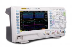
The last time I bought myself something for this hobby was at least 3 years ago, if not more, and I got a soldering iron. Oh, and a small drill press last year. Well, I'm thinking it's time for my 2017 splurge and I have in mind something more modern than my Leader analogue o'scope. It's a nice o'scope and spec'd to 200MHz but I saw something new and shiny on ePay...
Rigol DS1054Z Digital Oscilloscopes - Bandwidth: 50 Mhz, Channels: 4 | eBay
They seem to be quite popular and it might be just the ticket for building a NAP 160 look-alike 😎
Rigol DS1054Z Digital Oscilloscopes - Bandwidth: 50 Mhz, Channels: 4 | eBay
They seem to be quite popular and it might be just the ticket for building a NAP 160 look-alike 😎
Attachments
Last edited:
Bigun,
Looks very nice and inexpensive.... Why did you choose 4 channel, when you could get 100MHz with two channels at similar price?
HD
Looks very nice and inexpensive.... Why did you choose 4 channel, when you could get 100MHz with two channels at similar price?
HD
Member
Joined 2009
Paid Member
which do you think would be the most useful, 100MHz over 50MHz or ability to hook up extra channels ?
The rigol is meant to be easy to "mod" to get 100MHz, but only if you use 1 channel
1ch = 1GSa = 10 samples per second @ 100 MHz
2ch = 500MSa = 10 samples per second @ 50 MHz
4ch = 250MSa = 10 samples per second @ 25 MHz
from here"new-rigol-ds1054z-oscilloscope/
1ch = 1GSa = 10 samples per second @ 100 MHz
2ch = 500MSa = 10 samples per second @ 50 MHz
4ch = 250MSa = 10 samples per second @ 25 MHz
from here"new-rigol-ds1054z-oscilloscope/
Bandwidth is everything for checking stability, square wave response, loop gain behaviour, noise etc. and whilst you can get more than the nominal -3dB range out of a 50Mhz analog scope, digital types don't have a usable response much beyond their spec. and firmware settings.
100mHz doesn't seem that much more than 50MHz but a lot happens up there that only a 'scope can see. I guess it's a trade-off between facility and efficacy but if your test fundamental was a 20kHz square wave, you wouldn't see enough on the screen to be certain of what was happening.
Given that I couldn't use any more that a dual trace and only then for waveform comparisons and measurement, I can't see much need or benefit in multiple channel instruments for audio, other than for demonstration or illustration. I believe that manufacturers and service techs working to a budget on digital and complex control/monoitoring systems find plenty of uses though. 16+ channels is not unheard of there.
Last edited:
100mHz doesn't seem that much more than 50MHz but a lot happens up there that only a 'scope can see.
Agree. But what is it that we want to see up there in 100 MHz? Can we hear 100 MHz? Imho, many people focus too much on what happens up there without seeing the impact happens in audio band. I think this IS the key word with Naim amps. Not that this is special to Naim amp or topology, but JV seems to understand this critical "secret", showing that he had very good ears.
dd, designers and repairers of amplifiers need to measure more than just audio band limited signals. DIYs also need to measure DC voltages as well testing for signs of instability and EMI which, with Mosfet designs, can be in the 10-100Mhz range. The harmonic distortion products of audio alone can reach into the 100kHz region....Can we hear 100 MHz? Imho, many people focus too much on what happens up there without seeing the impact happens in audio band.
We need to see and verify that all is well in a new design or what is going on at high frequencies like instability or oscillation that affects audio, when there are fault conditions. We then have to decide what to do and then prove its effectiveness, quite apart from and beyond the frequencies of the amplifier's normal audio frequency range. There are very good reasons for using semiconductors with much higher Ft and switching speeds than audio too.
I think you will need to study some more on how amplifiers work and are kept stable. Its not something you can learn in a day though - It requires quite a bit of study and some formal experiments. Here's one of the best but not cheap introductions to understanding the generic Naim style of audio amplifier - the basics, operation, problems and solutions without needing a deep mathematical background.
https://www.amazon.co.uk/Audio-Powe...coding=UTF8&psc=1&refRID=99VY9W0RVA6W8JR7JC08
There is an earlier edition PDF here:
http://www.kelm.ftn.uns.ac.rs/literatura/mi/pdf/AudioPowerAmplifierDesignHandbook.pdf
dd, designers and repairers of amplifiers need to measure more than just audio band limited signals.
I know. I'm just saying that they miss the elephant in the room.
We need to see and verify that all is well in a new design or what is going on at high frequencies like instability or oscillation
That is the problem. It is not difficult at all to stabilize an amp, especially if sound quality is not a concern. I see 2 general mistakes: One, there are reasons why amplifiers have instability. Once this is understood, stability can be achieved automatically by paying attention on the cause not the effect and measurements etc will only needed to confirm.
Two, some Naim amps might have tendency to oscillate. Some people may think that they have read so many books and know very well how to stabilize an amp. They add compensations here and there and they do nothing but increasing stability and missing what Naim had tried to achieve in the first place.
I haven't studied Naim circuits, but I'm almost 100% sure I know what JV was trying to achieve in his amps. I just checked Bigun's Naim clone circuit and it is a total mess in term of this objective.
Have you considered a spectrum analyser?Well, I'm thinking it's time for my 2017 splurge
Unfortunately, that says that despite not studying Naim circuits, you can confidently criticise them - just by visual comparison perhaps? Are you sure that's what you want to say and you actually understand the operation of the amplifier section within the overall design?....I haven't studied Naim circuits, but I'm almost 100% sure I know what JV was trying to achieve in his amps. I just checked Bigun's Naim clone circuit and it is a total mess in term of this objective.
Don't underestimate Bign and his version. He's no newbie here and does have a grip on the electronics. If you read the OP, you'll see what he's attempting and it isn't to make simply a DIY clone of his own 🙂
That's not my experience: I find the earlier parts in the chain are more critical. I could not judge the quality of my amps without an excellent digital source whereas a modest speaker is fine. Obviously the distortions accumulate down the line. Also, in general, the distortions a modest speaker cause are less musically severe than those of a modest amp.Actually, the hardest part of listening like that is to judge which part of the sound is due to the speaker. This is important because speaker is the biggest determinant factor not the amp!
I would recommend to folk to divide their equipment budget unevenly. Spend twice as much on source as amp and twice as much on amp as speaker. At least spend more on the front end. 😎
How did you implement the separate supplies, e.g.: simple LPFs like Bigun is doing or regulators or even separate transformers etc?yes big power supplies within reason the bigger the better but its not all in one direction i can remember in 1979 learning a big lesson with power supplies i designed and build a power amplifier in which the front diff pair and vas were powered seperate from the drivers and output devices it also had a switch which coupled the front end and vas to the main supply The result was amazing in seperate drive mode the amplifier was faster the bass had more authority it really was a revelation this was just before the market went crazy with dual left right power supplies
I did discuss this with a no of well known designers of electronic amplifiers who in the course of time came out with revised front ends dealing with the result in new and interesting ways some of the guys are still alive some dead and like me some have in effect disapeared
Trev
Also interested in your opinions about using switch mode supplies for audio.
Last edited:
Even a 10 MHz CRT scope is usable as the fizzy bit one can't quite make out is the problem. My digital scope shows sine waves when a square wave input when in the lower MHz. To show a reasonable square wave one needs H19 to be shown. Thus in some ways 10 MHz is looking to show 190 MHz. We can get around this by saying even if we see a triangle wave that should be square is it looking like a triangle wave should. Even the sine wave if clean may tell us enough.
One thing digital lovers tend to overlook is if using my rule of thumb the last near square square wave we can get from a CD player is {44.1/2}/19 kHz = 1.16 kHz. I was a bit sad when a valve amplifer I built started to give up doing square waves at 2 kHz. Then I told myself " at least it's twice as good as a CD player ". I could have added a bit of tuned feedback to " cure " that. I didn't bother.
There is a theory that slightly unstable amplifiers sound better. That is ones that never kill themselves or speakers. I suspect that says the square wave is not exactly like music. However a 1 kHz squarewave is not far off.
Below is for very little money me building a 12 pole filter so as to measure a Hypex class D amplifier. I got the idea from Audio Prescission as they also have an add on device. The 50 kHz sine from square is due to the Hypex having output chokes to make sure the 400 kHz isn't passed to the speakers ( about -20 dB if memory is right ) . I was very surprised to see my results were identical looking to the AP graphs in Stereophile for the same amplifier. I was impressed to see how good the 5 and 10 kz square waves were considering the output chokes. The filter distortion wasn't fantestic. I had no choice as it was like a set of glasses, that or nothing to see the better picture.
Unfortunately, that says that despite not studying Naim circuits, you can confidently criticise them - just by visual comparison perhaps? Are you sure that's what you want to say and you actually understand the operation of the amplifier section within the overall design?
I can criticize the Naim sound by listening thru YouTube (it has too high distortion in general, above my minimum threshold). I can give thumbs ups for what it is good at (also thru YouTube).
I haven't studied Naim circuit (because I'm more interested with other topologies) but from information I can gather here and in other threads I guess JV knows what I know. If this is true, then I can tell that Bigun's circuit just doesn't have it.
I knew by running/examining the ASC file Bigun posted. I hope and believe it is just a preliminary design. It will not sound good enough that way. But ignore this, as Bigun knows more about electronics than I do.
That's not my experience: I find the earlier parts in the chain are more critical.
Here is a concept: plenty of goodies will be ruined by one mistake. No goodies is often preferable when there is no mistake.
The above concept applies to me regarding the sound system quality. One mistake, like too high a distortion, may ruin other goodies in a system.
The earlier parts (sources), are much closer to perfection than amplifiers and especially speakers. So guess which one has the bigger tendency to ruin the sound (assume impedance matching is not an issue)?
There is a theory that slightly unstable amplifiers sound better.
There is also the opposite theory. I think both are correct.
Amplifier sounds good when correct things are done such that stability is a result. Amplifier sounds good when wrong things are not done to correct stability issues 🙂
The Naim amp is if you like the " blameless " amp gone wrong. And wrong is better as it hasn't had it's second harmonic removed. The Cdom still is the worst part of the amp as with many in the " blameless " school. It could be if Cdom was fine tuned it will be musically blameless. The networks we see when Naim may assist this. I doubt there is enough current to drive Cdom when >39 pF.
- Status
- Not open for further replies.
- Home
- Amplifiers
- Solid State
- TGM10 - based on NAIM by Julian Vereker