I vote for d):
Two transformers, wired center tapped with two diodes per transformer. Both the rectified voltages are then connected at the central star ground accordingly. Better would be a transformer with two centre tapped windings (torody makes these without further costs).
If only one transformer can be used I vote for a) or b)
The right answer will be the one which meets your OP criteria. Will you make it a hybrid design by upgrading each design element based on performance merit or will you explore the Naim sound character by adhering as closely as possible to the original?
If the latter and you do want to explore more of the Naim topology, you might find some interesting things like what happens to sound quality when you isolate, regulate, filter etc. the front end supplies. Hugh Dean certainly found the importance of the supply rail integrity with his AKSA models and I know the effect it has on NAP SQ too. It's not good.
If the latter and you do want to explore more of the Naim topology, you might find some interesting things like what happens to sound quality when you isolate, regulate, filter etc. the front end supplies. Hugh Dean certainly found the importance of the supply rail integrity with his AKSA models and I know the effect it has on NAP SQ too. It's not good.
I fully agree, Ian.
Maybe it is why so many "Naim-Clone" projects failed to reach the goal to find out the "secret" about the "Naim-Sound", because almost all the projects started with some sort of modification already. Not that modifications are possible, but we should not complain if the project soundwise leads in some other direction.
That is why I opt for the original power supply solution of the better Naim amps and preamps. The 110/140 used a simpler approach.
Member
Joined 2009
Paid Member
The power supply capacitor footprint is on the pcb and this places a constraint on choices. The capacitors I have chosen are Nichicon UKW series designed for audio. The part number is UKW1H472MRD, providing 4,700uF rated to 50V.
Soundwise, the front-end rail decoupling capacitors (which go beyond the basic Naim design) are possibly more important. Here again I've selected a Nichicon UKW series cap. The part number is UKW1H331MPD1TD, providing 330uF rated to 50V.
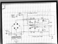
I think option b) has the technical advantage that it avoids imbalance of dc currents from + and - rails from unbalancing the secondary windings. But if I were to stay with the NP 140 topology, i.e. option c) the circuit would look something like the attached drawing.
Soundwise, the front-end rail decoupling capacitors (which go beyond the basic Naim design) are possibly more important. Here again I've selected a Nichicon UKW series cap. The part number is UKW1H331MPD1TD, providing 330uF rated to 50V.
I think option b) has the technical advantage that it avoids imbalance of dc currents from + and - rails from unbalancing the secondary windings. But if I were to stay with the NP 140 topology, i.e. option c) the circuit would look something like the attached drawing.
Attachments
Last edited:
Don't bring the speaker return to the middle of the PSU charging circuit.
Separate the first stage charging from the second stage charge. And so on till you reach the last stage charging. As your zero volts moves further from the rectifier/centre tap the spikyness of the charging current reduces.
Take a tap off the last zero volts and run this to your Main Audio Ground (MAG) along with the V+ and V-.
Use the MAG as your voltage reference. But don't split your close coupled pairs. Only bring those (very few) wires that are voltage references to this point.
Your centre tap is shown separated from the two other current carrying charging wires. You may have done this just for clarity in the diagram. But you need a twisted triplet from transformer to bridge rectifier, and a further twiested triplet from rectifier to first smoothing cap pair. Continue with those twisted triplets until you reach the amp PCB, where the three power inputs should be in a very close coupled group. NOT on the opposite corners of the PCB.
Last edited:
We might need a diagram, Andrew.
@Bigun: You want to avoid having the PCB star grounds at different voltages as they will be connected via your input cables. You need to make sure no PSU currents flow around your input cables. Usually you would make sure your input cable grounds for each channel go to a common ground point.
The obvious wiring method is to use separate transformers and keep the smoothing caps on the PCBs as you have them now. If you use a common transformer then locate the smoothing caps off the PCBs so they are all grounded at one point (like Naim NAP250). Or mimic two transformers with a transformer with dual, centred-tapped secondaries; although there is still coupling between the secondaries.
If you want to stick with your current transformer and 2 star grounds you will have to think it through. I haven't used this arrangement so I can't comment from experience.
Member
Joined 2009
Paid Member
I understand what Andrew is recommending and I agree. And also agree with Bryan that we want to avoid creating a ground loop through the input cables but this is why I have introduced a signal ground-lift resistor into the design; something Hugh has always recommended.
The pcb layout is finished already and it has a single and sold star-gnd layout. However, I will look at your suggestions to position a couple of off-board capacitors alongside the rectifier in order to better isolate the amplifier from the worse of the charging pulses and also to keep the rectifier current pulses in as small a physical loop area as possible. I need to go and take stock of the mechanical constraints, the boxes I have are rather small.
The pcb layout is finished already and it has a single and sold star-gnd layout. However, I will look at your suggestions to position a couple of off-board capacitors alongside the rectifier in order to better isolate the amplifier from the worse of the charging pulses and also to keep the rectifier current pulses in as small a physical loop area as possible. I need to go and take stock of the mechanical constraints, the boxes I have are rather small.
Gareth,
I have slightly amended my usual earthing methods in recent times.
I have found that the IEC power/chassis ground is inclined in some systems to inject a lot of hum into the amp output. I had normally connected the two with back to back diodes and a parallel 10R.
To ensure the amp power ground is still within safe connection to the IEC power/chassis, I drop the 10R resistor. If the pd between amp earth and power/chassis earth exceeds +/-0.6V it is routed through one of the diodes, which must be left in place.
This approach removes any power earth hum and noise.
HD
Member
Joined 2009
Paid Member
I have been doing something similar in that I connect the power amplifier power-ground to the chassis through back-to-back diodes with no resistors. But the signal ground I keep the option to isolate through a resistor from the power amp ground.
Hugh - have you ever considered for your own system (at home) the benefits of a single cable for interconnects with DIN plug/socket like NAIM instead of two RCA cables with separate earths and hence implied ground loop ? - I've not had any issues with RCA but they plugs/sockets always look a bit noddy to me and I have thought about using something more substantial.
Hugh - have you ever considered for your own system (at home) the benefits of a single cable for interconnects with DIN plug/socket like NAIM instead of two RCA cables with separate earths and hence implied ground loop ? - I've not had any issues with RCA but they plugs/sockets always look a bit noddy to me and I have thought about using something more substantial.
Yes, Gareth. I agree.
Some sources have their stereo outputs both connected at ground.
Some do not; maintaining independent output grounds.
Both systems must be accommodated in a versatile power amp.
I maintain independent grounded inputs so that the second option maintains its integrity.
I have tried connecting the two RCA grounds at the rear of the amp, then running a connection to the amp power ground. I'm not so sure on this method, but one respected friend believes this is quieter. My though is that this bypasses the usual 10R connection I maintain between signal earth and power amp - which I set up right at the module.
I do use independent rail supplies (separate bridges too), with no center tap. The amp power earth is at the module, and the electrically midway between the two rails. Input signal ground and fb ground are taken to this ground via a 10R ground lift. This really seems to work well, but it's something I have achieved only a lot of hard work. Earthing is a black art and everyone has a different view.
HD
I vote for d):
Two transformers, wired center tapped with two diodes per transformer. Both the rectified voltages are then connected at the central star ground accordingly. Better would be a transformer with two centre tapped windings (torody makes these without further costs).
If only one transformer can be used I vote for a) or b)
This option d) doubles copper losses in the secondary winding. In a given winding space, you need twice the turns number, thus have to reduce the cross section of the magnet wire by half, thus doubling ohmic resistance. This sadly is common to all two-diode full wave rectified supplies.
With option d) you could also use these nice double schottky diodes.
Are there any nice double Schottky diodes with common anodes? Never seen some. So, for your approach the common cathodes of 'nice' double Schottkies in the negative rail need to be tied to ground, while the CT goes to the filter cap's negative leg.
With two separate transformers, or with two independent, center-tapped secondaries, or with four independent secondaries on a single one, I'd vote for double option a) and build virtually two mono amps in one case.
Best regards!
Last edited:
Member
Joined 2009
Paid Member
Hi Kay,
Unfortunately, my case isn't large enough for a true double mono build. But I agree with you that this is an ideal approach, in general.
Unfortunately, my case isn't large enough for a true double mono build. But I agree with you that this is an ideal approach, in general.
This option d) doubles copper losses in the secondary winding. In a given winding space, you need twice the turns number, thus have to reduce the cross section of the magnet wire by half, thus doubling ohmic resistance. This sadly is common to all two-diode full wave rectified supplies.
Are there any nice double Schottky diodes with common anodes? Never seen some. So, for your approach the common cathodes of 'nice' double Schottkies in the negative rail need to be tied to ground, while the CT goes to the filter cap's negative leg.
My suggestion results from Naim and also my own experience. I am completely fed up about some smartasses out there telling that is is crap for whatever reasons. Do whatever you want, but then do not complain that the result is not what you have expected.
(Do not forget to look at the posted images...)
Last edited:
Member
Joined 2009
Paid Member
I think all the approaches are valid, we all get to pick what we like to use. Sometimes I like to choose an approach because it is the 'wrong' way, just because I can, it's just a hobby and so it's up to me and only me 😀
It's interesting how Naim also went through an evolution of their psu designs, technically improving them and ultimately to full regulation. When I read reports from people who have lived with different Naim units they still have a fondness for the technically weaker solutions. This interaction between psu and amplifier is another area of design that is available for exploration.
It's interesting how Naim also went through an evolution of their psu designs, technically improving them and ultimately to full regulation. When I read reports from people who have lived with different Naim units they still have a fondness for the technically weaker solutions. This interaction between psu and amplifier is another area of design that is available for exploration.
Agreed!
Since you wanted to find out if there is something special about these amps, I recommend to start from the knowledge we already have. I am not recommending to stop there, but if we start from somewhere we will also end somewhere, maybe not where we wanted to go.
In the NERO amplifiers we have also started from a well proven and established stand - and then developed from there. You may call that tweaking, modification or real development. With simple amplifier circuits every detail counts.
I will continue to read this thread but I guess I have little to contribute when things drift off significantly. No problem with me.
Member
Joined 2009
Paid Member
I will continue to read this thread but I guess I have little to contribute when things drift off significantly. No problem with me.
Not so fast! - I welcome a continuous flow of advice and it's good for those that just lurk around the forum who only like to read - to learn what the more active members have to contribute 🙂
- Status
- Not open for further replies.
- Home
- Amplifiers
- Solid State
- TGM10 - based on NAIM by Julian Vereker