Yes, this example was a "chrome bumper" series NAP model, where their outer case or sleeve was just a short length of RHS alloy beam extrusion. As you can see, their chassis would have been a close fitting, 3mm sheet alloy drawer in the extruded case sleeve. I was impressed in the 1980's when I saw them demo'd in the shop I frequented. I was even asked to pull a few other pieces apart for display and some were actually very high tech studio gear, not domestic amp/preamps at all, having many large, upright daughter boards full of SMDs back even then. I assumed they were custom builds for a studio, as I've not seen quite the like anywhere since.
...
Naim of course did not have any interest in the ruinous marketing practices still common in most of the local press (for a good review you have to order ads for a year and give away the amps for free for the reviewer)....
This is complete nonsense and a myth that keeps being repeated. I have been involved in two businesses with international profiles and product reviews in a wide variety of hi-fi publications. Never once has a review been linked to advertising spend, or a free product been required. The magazines need the products to review, that's what drives their readership.
Sent from my x600 using Tapatalk
Bigun,
I suggest that you use BNC connectors as NAIM did in some pre/power combinations. Nothing beats them for the quality of signal transfer.
I suggest that you use BNC connectors as NAIM did in some pre/power combinations. Nothing beats them for the quality of signal transfer.
Nico yes i am fine with the current limiting seen that from Quad works solid rock under any pressure
Point is that this was only one of the models the rest issues like that was simply covered by any sense that vbe will be taken from inside the chassis ...
Obviously and with that amount of low bias you have a machine that will behave according to the room temperature and over/compensation or under/compensation will eventually occur together with ages to warm up in low or very low original bias set at the factory .
As a closing argument to my understanding the all above procedure is not a situation that is calculated or a product of study because if so they will very soon realize the effect of ambient temperature...IMHO i think that its just a rough calculation based on luck and nothing else .
In many Japanese amplifiers this issue is a product of study meaning that a Vbe will preserve a bias within a specific temperature margin and overcompensate above that point ...so a vbe will be acting as a safety measure in a way .
Some Japanese amplifiers have been so well calculated ( don't really refer to expensive amplifiers simple things like the Luxman L31 ) that is enough to set the trimmers in the middle point and "automatically" both bias and offset will be within a desirable level ...That is not by accident ....choice of values and parts is very well calculated and the Japanese have been masterminds in that ....
Last edited:
On the other hand i never understood the principal of Quasi and the various opinion about that and my estimation is that quasi existed at the times that proper complementary transistors was impossible to manufacture.
Quasi manufacturers / designers scream for quasi since upper and lower transistor will share similar characteristics but isn't this pointless when the lower transistor is CFP configured ?
I think i will have to study Bryston .....
Quasi manufacturers / designers scream for quasi since upper and lower transistor will share similar characteristics but isn't this pointless when the lower transistor is CFP configured ?
I think i will have to study Bryston .....
We are discussing the issue with my employees in the lab and one of them just said :
Yes obviously upper and lower transistor will share the same behavior and characteristics only they can do that outside the amplifier:D😀😀😀😀
Yes obviously upper and lower transistor will share the same behavior and characteristics only they can do that outside the amplifier:D😀😀😀😀
On the other hand i never understood the principal of Quasi and the various opinion about that and my estimation is that quasi existed at the times that proper complementary transistors was impossible to manufacture.
Proper complementary is still inexistent or so, but at the time that was a matter of prices, the PNP complementary was several time more expensive than their NPN counterparts.
What wasnt available were complementaries of NPN epitaxial transistors wich were extremely fast, like the much used BDY56 that had about the same characteristics as a 2N3055 but with a 120V VCE and an impressive Ft wich was at worst 10MHz.
Otherwise as 2N3055 complementary the most used in Europe FI was the BDX18/18N.
while at the same time average consumer Japanese amplifier had transistors with 30Mhz ft ....
It's a long time since I built any equipment with DIN sockets/plugs.The reason I was interested in cables is not so much to stir up that old nest but to decide whether to go with RCA connectors, which I normally do, or introduce a DIN connector to the chassis in the spirit of what is traditional Naim. I haven't started to do the drilling and filing of the chassis yet. I don't have any experience with DIN connectors or cables, but maybe one cable instead of two RCA's has an appeal. And because this is DIY it's fun to do things a bit different from the mainstream - but with a good reason.
But I chose them because they are convenient for multiple signals.
3pin, 4pin and 5 pin are available for a wide variety of connection requirements.
If it wasn't for compatibility with other gear I would have stayed with DIN.
The numbering system used by Naims is the short term total power power into 4r0 dummy test loads from their 8ohms rated amplifiers.According to Naim's web page, the NAP250 is rated at 80W pc 8 ohms. I understand from a thread in this forum that the psu rails are +/-40V. The max theoretical average sinewave power into 8 ohms is 100W. So Naim are underestimating if anything and using average power rather than peak. So by your reckoning, they have never sold any NAP250s? 😉
So a Nap250 is really 125W+125W into 4r0+4r0.
That for an 8ohms rated reactive load is roughly 70W into 8ohms, 80W is pretty close and may well be achieveable if the bridged output into 4r0 has drooped due to the way a bridged amplifier is stressed by it's load.
Similarly a NAP140 is 70+70W into 4r0+4r0 and probably indicates around 40W into 8ohms.
Ian F has clearly done his homework.
The NAP250s are regulated supply designs and the power rating conferred by the "250" is a nominal figure for the sum of both channels driving 4 ohm loads. i.e. 2 x 125W = 250W. This is the basis for all the NAP series model numbers.
Last edited:
Soon after HiFi World started up their editorial stated they would not be joining the "old boys club" and would print real reviews and not be influenced by advertisers and the pressure they can bring.This is complete nonsense and a myth that keeps being repeated. I have been involved in two businesses with international profiles and product reviews in a wide variety of hi-fi publications. Never once has a review been linked to advertising spend, or a free product been required. The magazines need the products to review, that's what drives their readership. ...........
Last edited:
Member
Joined 2009
Paid Member
I suggest that you use BNC connectors as NAIM did in some pre/power combinations. Nothing beats them for the quality of signal transfer.
I've used BNC before (for my PhD project maaaaany moons ago) but there is an attraction to having multiple signals with one wire. My plan is to include RCA, it's simply silly to leave it out. But if I have space my thinking is to include a DIN socket as an option.If it wasn't for compatibility with other gear I would have stayed with DIN.
Yes obviously upper and lower transistor will share the same behavior and characteristics only they can do that outside the amplifier

I can give the benefit of the doubt to a number of magazines, but I still find the quality of reviews relatively poor and to be honest they are not very helpful. But I do like the glossy photos.Soon after HiFi World started up their editorial stated they would not be joining the "old boys club" and would print real reviews and not be influenced by advertisers and the pressure they can bring.
Bigun, have you seen the price of these Avondale NCC200s? £327! I think you should turn this project into a business. 
Member
Joined 2009
Paid Member
Turning a hobby into a business tends to kill the hobby (I've done it twice over the years). These days I don't have the time to do it again and I don't see it being worth the effort unless large $ are possible - do you want to make a proposal 😀
It is nice to make my own design choices freely, without hindrance from commercial constraints.
It is nice to make my own design choices freely, without hindrance from commercial constraints.
while at the same time average consumer Japanese amplifier had transistors with 30Mhz ft ....
Only during the late 70s, otherwise their only advantage was to have complementary pairs somewhat faster than the 3055/BDX18..
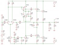
Other than this i once simulated this Naim amp and frankly it s not a good design fom the very start, as pointed by Bigun it is extremely prone to oscillations.
Among the bad things is the 22K resistance that load the differential, it is the cause of a huge miller effect that limit the bandwith of the return path, creating a huge spike in the frequency response.
Second is the baxandall diode of the quasi complementary stage, a 1N4148 is inadequate and could well end as a short that would increase hugely the OS current.
IMO quasi complementary OSs should be definitly abandonned as these are much less stable than the usual EFs, and their THD distribution which often produce mainly even harmonics is of no help since the distorsion is higher anyway.
Member
Joined 2009
Paid Member
Thanks for highlighting this, I hadn't thought that issue through properly. In fact, in my TGM1i, an AKSA clone, I included the provision for such a resistor as I remembered reading that 'SandyK' had himself included one in the early days of AKSA tweaking. The idea was to equalize the dc voltage at both of the LTP collectors to match Early effect. I had failed to think what happens at ac.the 22K resistance that load the differential, it is the cause of a huge miller effect that limit the bandwith of the return path
This surprises me, I thought these diodes were pretty robust but then again, I have not considered all the possible fault conditions that could stress it.the baxandall diode of the quasi complementary stage, a 1N4148 is inadequate and could well end as a short
Generally I never had any problems with the basic 1N4148 diodes.
In the classic Naim circuit there are three per channel. The two diodes in the first CCS can easily be substituted with a transistor like Naim does it nowadays. The Baxandall diode is critical and can be substituted with a more linear device like a transistor (wired as a diode, like a npn transistor where base and collector is connected).
In the Elektor Hybrid Amp from 10/2007 the Baxnandall diode is substituted with a 2SC1815 BL - the measured distortion was lowered to more than half. But only the BL type (hfe >350) works well, with GR, Y, or O types there is little difference to the diode.
I unfortunately have never tried that but I think it is a very good idea. In this project with a quasi-complimentary output stage one should make no compromises. If I will make another Naim style amp again I will defintely use that approach.
(I had a nice paper from JLH about the effect of this diode but it is lost in the labyrinths of my archive.)
Last edited:

A slight revision of the schematic on post 1, there s much less components, particularly all the useless ones that were here just to compensate for the flawed starting point.
An EF OS would have lower THD, what the quasi complementay does is to increase distorsion with even harmonics being increased more than odd ones...
An EF OS would have lower THD, what the quasi complementay does is to increase distorsion with even harmonics being increased more than odd ones...
Attachments
Member
Joined 2009
Paid Member
The Baxandall diode is critical and can be substituted with a more linear device like a transistor (wired as a diode, like a npn transistor where base and collector is connected).
I can believe that. I have Bob Pease book "Troubleshooting Analog Circuits" and he shows that the diode-wired transistor makes for a better diode.
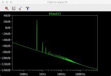
As for the distortion, well this is one of the key things about the amp that makes it what it is. I'm OK with the distortion. It looks just fine in Spice - Wahab is right in that it has predominant even harmonics. We're looking to make a circuit like the old Naim amp. If we want to make an amplifier with lower distortion that would be a different project (look up my TGM7, TGM8 amps).
Attachments
Last edited:
- Status
- Not open for further replies.
- Home
- Amplifiers
- Solid State
- TGM10 - based on NAIM by Julian Vereker