BWRX said:I haven't had time to build a second channel or even do any more listening for that matter. I've had to stay late at work and my girlfriend needs attention 😉 but I was able to solder 8 TAS5261 chips onto boards tonight before I left work.
I wil post an updated parts list when I make changes to my current BOM. Don't worry, there weren't any drastic changes.
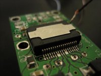
Attached is a photo showing a sample of my hand soldering.
PFFT!
Here is a sample of my hand soldering using a $6 25w iron with standard tip and no magnification.

Attachments
Pushahhh ... why, back in the really good old days, I used to solder cat's whiskers right to the crystal ....
Whooo Haaaa ....
Whooo Haaaa ....
As far as I know, the following folks want me to solder the chips but I have not received anything from you yet: GeWa, ericallan, SmellofPoo, and Bearman.
No need to solder anything on the boards for me Brian. I thought I mentioned that already in a PM to you.
Regards
You probably did mention it Walter. I went back through all my emails to see who wanted what and could have missed it. Thanks for letting me know 🙂
Official Bill of Materials for the TPA2001D1-TAS5261EVB
Attached is the official TPA2001D1-TAS5261EVB BOM including Digi-Key part numbers for the parts that will be included in the parts kits. You can of course substitute parts as long as they meet or exceed the specs of the parts they're replacing. As always, pay careful attention to component size, footprint, voltage rating, thermal rating, etc. when using different parts.
Attached is the official TPA2001D1-TAS5261EVB BOM including Digi-Key part numbers for the parts that will be included in the parts kits. You can of course substitute parts as long as they meet or exceed the specs of the parts they're replacing. As always, pay careful attention to component size, footprint, voltage rating, thermal rating, etc. when using different parts.
Attachments
Hi Brian
Did you set up two boards for an official listening session?
I'd like to read something before we start soldering: maybe you will have mods to suggest.
Ciao
Thomas
Did you set up two boards for an official listening session?
I'd like to read something before we start soldering: maybe you will have mods to suggest.
Ciao
Thomas
No, I still haven't had time to build up my second board. I did, however, start labeling the parts for the parts kits. I'm going to work on that some more tonight. Hopefully this weekend I will get to build up another board and do a stereo listening test. The next two weeks at work will be a killer for me because I'm the lead developer for a new product and we (actually my boss and the president of the company...) committed to ship prototypes before the holiday season 🙄 Like they'd do anything with it over the holiday even if they had it...
The kits are coming together. I've made my way through about half of the parts list so far and should be able to finish up the rest later today. That means I will be able to start shipping these out this week 🙂
I underestimated the cost to ship these things with the weight of all the parts and the toroid cores so you guys got a bit of a break on that
I underestimated the cost to ship these things with the weight of all the parts and the toroid cores so you guys got a bit of a break on that
Attachments
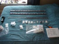
Oh, boy ... the parts spread on the bed ....
(I'm a kitchen table man myself)
Any updates to the BOM parts lists, docs or images?
(I'm a kitchen table man myself)
Any updates to the BOM parts lists, docs or images?
FastEddy said:Oh, boy ... the parts spread on the bed ....
(I'm a kitchen table man myself)
Any updates to the BOM parts lists, docs or images?
I used my bed because then I have to get it done or it means I'll be sleeping on the floor 😉
The BOM is the same as the last one I posted here: http://www.diyaudio.com/forums/showthread.php?postid=1074907#post1074907 I'm working on a component placement diagram that will help to find component locations when building up the boards. The general rule when building up boards is to solder on all the components with the lowest height first and work your way up to the tallest components. For these boards it's probably easiest to solder all the components on the chip side first so the board stays flat the longest. I often use a 1/4" thick piece of foam rubber about 2" by 6" under boards to help keep them more stable if components are on the underside. It also keeps them from moving around since the foam grips the board and the work surface nicely.
I'm still waiting for the correct value resistors for R31 to arrive on Friday so I can finish putting the parts kits together.
Get a good nights sleep ... I do these kinds of things first thing in the AM, then play ... then nap ... then work a little more before dinner ... but sleeping on the floor is good for you
A little update.
I'm still waiting for ONE part (the 453 ohm resistor DigiKey messed up on my previous order) to arrive because UPS conveniently delayed the shipment that was supposed to arrive on Friday until Monday 😡 but I currently have 5 orders ready to be shipped out except for that one part. The 5 orders are for those who have already paid: FastEddy, dmigo, pinkmouse, ericallan, and jajabin. Everything for two full kits fits nicely into a 6"x9" padded envelope and I hope will weigh less than 4 lbs. If you go over 4lbs the price goes up more than you'd think it would...
I've already sent out the orders for thomaseliot, Markus2006, and SmellofPoo. I know Thomas and Markus have received their packages but haven't heard anything from Gerd yet.
I'm trying hard to get the rest of the orders ready to ship out this week, so if you haven't sent me payment yet now would be the time to do it. I'll try to send out emails tomorrow to those who haven't.
Has anyone tried using the TAS5261 in a self-oscillating design?
The reason for asking is that the 5261 has an internal PWM detector that tri-states the outputs if no PWM transition occurs for 13usec. In a UCD (or similar) design that is driven into clipping, the PWM transitions can stop for periods exceeding this.
If the chip tri-states the outputs, then it is possible that a self-oscillating amp will stop oscillating and not restart.
Apologies if this point has been raised already.
AFAIK, we are not discussing a self oscillating design here at all, the PWM is driven from another chip that I believe has its own clock. Were you thinking of trying something different?
BWRX said:If you go over 4lbs the price goes up more than you'd think it would...
Might be cheaper just to send two small packets, I've been caught out on this before.
No rush anyway on mine, my current project is trying to get my iMac back to life. Just like Prof Frankenstein, I need a good lightning storm!

Hi Pinkmouse. Yes, I am about to try the 5261 as the output stage of a UCD-like amplifier. I realised this thread was for the normal clocked operation of the chip, but wondered if anyone might have had a go at using it as part of a self-oscillating design.
The alternative for me is to use the NXP (Philips) TDA8939 instead, but I'm a little concerned that the data sheet for that is dated 22nd April 2004 and is still shown even today as an 'Objective Data Sheet', which doesn't inspire confidence!
Thanks.
The alternative for me is to use the NXP (Philips) TDA8939 instead, but I'm a little concerned that the data sheet for that is dated 22nd April 2004 and is still shown even today as an 'Objective Data Sheet', which doesn't inspire confidence!
Thanks.
Hi Ouroboros.
No, I really doubt anyone has.
The simple solution would be to not drive the output stage into clipping. The difficult part about doing (or trying to) a self oscillating design around this chip is that it requires 0-3.3V PWM inputs. The outputs are bridged, so 0V for them is around half of the power supply voltage.
Ouroboros said:Has anyone tried using the TAS5261 in a self-oscillating design?
No, I really doubt anyone has.
Ouroboros said:The reason for asking is that the 5261 has an internal PWM detector that tri-states the outputs if no PWM transition occurs for 13usec. In a UCD (or similar) design that is driven into clipping, the PWM transitions can stop for periods exceeding this.
If the chip tri-states the outputs, then it is possible that a self-oscillating amp will stop oscillating and not restart.
The simple solution would be to not drive the output stage into clipping. The difficult part about doing (or trying to) a self oscillating design around this chip is that it requires 0-3.3V PWM inputs. The outputs are bridged, so 0V for them is around half of the power supply voltage.
pinkmouse: " ... my current project is trying to get my iMac back to life. ..."
Check out the newer Mac Mini / MacBook / iMac all have Apple "Lossless" optical audio outputs, built in ... 🙂 ... and FireWire ports = for pro audio work.
Check out the newer Mac Mini / MacBook / iMac all have Apple "Lossless" optical audio outputs, built in ... 🙂 ... and FireWire ports = for pro audio work.
- Status
- Not open for further replies.
- Home
- Amplifiers
- Class D
- Texas Instruments TAS5261