BWRX said:No smoke yet!
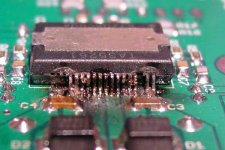
Well, there still hasn't been any smoke, but earlier this morning there was quite a shower of sparks that came from my desk while testing near full power... You can see the extent of the damage in the attached photo. No other component showed visible damage. I'm not sure exactly what caused such a catastrophic failure, but the TAS5261 wasn't the only part that bit the dust. Also on the casualty list was the TPA2001D1 and the two zener diodes that serve as the reference for the 12V gate supply transistors (not sure how they could have been fried unless a very high surge current was drawn through the gate supplies when the 5261 failed). Surprisingly nothing else was bad, including the bypass caps right next to the power pins of the TAS5261. Even so, I replaced them and the other dead parts earlier today, as well as changed the values of a couple others, and the board is up and running again.
Amazingly enough there was zero damage to the PCB except for some solder mask that was vaporized along with the power pins of the chip. Now that's a quality PCB!
While I'm not too sure, my gut feeling is that the damage was caused by my wiring job and the TPA2001D1 sending a not so nice signal to the 5261. I had some very bad pops, noise, and oscillation on my test speaker when I had just connected the input ground and signal to the INN and INP on the board. But I forgot that INN and INP are connected to the 2001 through coupling caps. When I connected the 3.3V supply ground to my preamp ground all the humming, popping, and harsh noise went away.
My ground wire between the two was less than optimal, as it wasn't even soldered (don't be careless when dealing with higher power circuitry), and could have moved around and caused a pop or transient that the 5261 tried to replicate but could not and a result failed quite spectacularly.
One change I made was to raise the value of the current limiting resistor to 27k which should lower the current limit threshold to something around 13A. Even though the current limiting protection circuitry isn't fast enough to stop a current surge similar to what may have happened in my situation, every bit helps while testing.
Attachments
Member
Joined 2004
Xit happens 
Now the best thing is try to find out what happened and make it safer 😉
But as you said, I bet that the poor wiring caused this disaster. But limit the device current for a safer value is a good idea 🙂
Best Regards,
Fernando
Now the best thing is try to find out what happened and make it safer 😉
But as you said, I bet that the poor wiring caused this disaster. But limit the device current for a safer value is a good idea 🙂
Best Regards,
Fernando
" ... I'm not sure exactly what caused such a catastrophic failure, but the TAS5261 wasn't the only part that bit the dust. ..."
Dust, cat hair, belly button lint ... contamination between the chip leads?... Any of these plus minute solder errors or trace spacing ... happens all the time. 😡
I hope you don't use up too many boards & chips before you discover the root causes ... keep the faith.
(13 amps is quite an electron flow for those tiny traces. If you can isolate which one blew up first or is at the center of the burn area, then you might have the answer.)
All joking aside, I was pretty pissed when I saw the sparks fly. I hate seeing things blow up like that mainly because then I know I have repair work to do.
There wasn't any contamination between the pins because I thoroughly cleaned the board off with a brush and denatured alcohol. I cleaned the board even better after I replaced the chips and the other components.
I've got some spares of all the parts but unfortunately the 5261 chips are the ones I need to be careful with. I don't think I'll use up any other boards because if the board wasn't harmed after that last incident I don't see how you could unintentionally damage it otherwise.
You can see in the photo that the PVDD pins on both sides of the chip were what fried, not the traces connecting them to the caps. The PGND and output pin connections looked intact for both bridges, so high currents killed the high side mosfet first on BOTH bridges. Keep in mind that the PVDD pins for each bridge are electrically separate on the PCB and are connected together back at the positive terminal of the large 33,000uF cap. There are schottky diodes between the output node and ground and the output node and the PVDD rail so that if the output node voltage swings a diode drop above the PVDD potential or a diode drop below the ground potential, the diodes will conduct and prevent the voltage from going any higher or lower which can damage the chip. It's possible that the initial overshoot of the PWM output signal caused the upper diodes to conduct and boost the rail voltage above the breakdown voltage of the internal FETs, causing them to break down and fail short circuit.
That's one theory anyway...
Tonight I'm going to work on getting the easy orders ready to ship then I will start working on putting the parts kits together during the week. This weekend was busier than I expeceted and I didn't get as much done as I expected.
FastEddy said:Dust, cat hair, belly button lint ... contamination between the chip leads?... Any of these plus minute solder errors or trace spacing ... happens all the time. 😡
I hope you don't use up too many boards & chips before you discover the root causes ... keep the faith.
13 amps is quite an electron flow for those tiny traces. If you can isolate which one blew up first or is at the center of the burn area, then you might have the answer.
There wasn't any contamination between the pins because I thoroughly cleaned the board off with a brush and denatured alcohol. I cleaned the board even better after I replaced the chips and the other components.
I've got some spares of all the parts but unfortunately the 5261 chips are the ones I need to be careful with. I don't think I'll use up any other boards because if the board wasn't harmed after that last incident I don't see how you could unintentionally damage it otherwise.
You can see in the photo that the PVDD pins on both sides of the chip were what fried, not the traces connecting them to the caps. The PGND and output pin connections looked intact for both bridges, so high currents killed the high side mosfet first on BOTH bridges. Keep in mind that the PVDD pins for each bridge are electrically separate on the PCB and are connected together back at the positive terminal of the large 33,000uF cap. There are schottky diodes between the output node and ground and the output node and the PVDD rail so that if the output node voltage swings a diode drop above the PVDD potential or a diode drop below the ground potential, the diodes will conduct and prevent the voltage from going any higher or lower which can damage the chip. It's possible that the initial overshoot of the PWM output signal caused the upper diodes to conduct and boost the rail voltage above the breakdown voltage of the internal FETs, causing them to break down and fail short circuit.
That's one theory anyway...
Tonight I'm going to work on getting the easy orders ready to ship then I will start working on putting the parts kits together during the week. This weekend was busier than I expeceted and I didn't get as much done as I expected.
Hi Brian
What kind of transformer have you?
Here are specs from TAS5261 datasheet for PVDD:
I never payed attention to that maximum of 52.5V.
What kind of transformer have you?
Here are specs from TAS5261 datasheet for PVDD:
PVDD_x Half-bridge supply voltage: min 0 nom 50 max 52.5 V
I never payed attention to that maximum of 52.5V.
I didn't thoroughly examine the PCB layout ... looking for trace problems (trace too small, traces too close, etc.). Thirteen Amps is about 8 X 10^24 electrons = enough to weld steel ...
What do you think here?
😕
What do you think here?
😕
thomaseliot said:What kind of transformer have you?
I never payed attention to that maximum of 52.5V.
I have a 250VA with 30VAC secondaries. The rail voltage is about 46V with a nominal 120VAC line voltage, a 25A IR bridge rectifier, and a 33,000uF filter cap.
The maximum recommended voltage between the PVDD and PGND pins is 52.5V but the absolute maximum rating is 71V. It should be able to withstand a reasonable overshoot without damage. I wasn't watching the switching waveform when the chip went into fireworks mode so I didn't see what kind of overshoot there was. It's hard to accurately capture that sort of event on my scope anyway.
FastEddy said:I didn't thoroughly examine the PCB layout ... looking for trace problems (trace too small, traces too close, etc.). Thirteen Amps is about 8 X 10^24 electrons = enough to weld steel ...
The power traces are as wide as three pins near the chip and as wide as the large cap pads elsewhere. 13A is a lot, but it's only a pulse unless the output is near the maximum rail voltage into a 4 ohm load. Don't forget the PCB is 2oz copper as well.
13A is also enough to vaporize the pins on a PSOP-36 part 😉
Hi Brian
The max supply is 52.5V!!!
The 71V is a short peak (ns) at the bootstrap node
You need to regulate the supply not to exceed the 52.5V, unless you want to keep changing TAS5261......
rgds,
Kim
The max supply is 52.5V!!!
The 71V is a short peak (ns) at the bootstrap node
You need to regulate the supply not to exceed the 52.5V, unless you want to keep changing TAS5261......
rgds,
Kim
kims said:You need to regulate the supply not to exceed the 52.5V
Hi Kim,
Does the TAS5261 need a regulated PS?
Kim, I have to ask you a private question (I hope other guys will forgive me). It's because you don't allow sending messages directly to you :-(.
I'm building a power amp based on TAS5100 (and TAS5010). I already got printed boards but there is one problem - I cannot buy TAS5100. It is not manufactured anymore and I cannot find a replacement for this chip. Is there a chance that somewhere in Copenhagen, in a locker there are 2 spare TAS5100s? I would be very grateful.
Marek
Hi Marek
Gues why I dont allow sending emails ;-)
As is stated on the www.ti.com the TAS5100 is obsoleted and the recomended replacement is the TAS5111, or even better the newer TAS5142.
you need to bluewire or update the PCB.....if you change to the TAS5111 its only a few pins that need changes
rgds,
Kim
Gues why I dont allow sending emails ;-)
As is stated on the www.ti.com the TAS5100 is obsoleted and the recomended replacement is the TAS5111, or even better the newer TAS5142.
you need to bluewire or update the PCB.....if you change to the TAS5111 its only a few pins that need changes
rgds,
Kim
TAS5261 = " ... <0.09% THD+N at 1 W ..."
TAS5142 " ... <0.1% THD+N at 1 W ..."
TAS5111A " ... Half Power THD + N @ 1 kHz (%)(kHz) 0.025 ... 70-W RMS Power (BTL) Into 4 [ohms] With Less Than 0.2% THD+N ..."
TAS5111 " ... Half Power THD + N @ 1 kHz (%)(kHz) Less Than 0.01 ... 70-W RMS Power (BTL) Into 4 [ohms] With Less Than 0.2% THD+N ... "
Too bad that the pin outs are all different or we could all build one board and try out each chip.
😱
Is it because you don't have TAS5100 in your locker 😀 ?kims said:Hi Marek,
Gues why I dont allow sending emails ;-)
Thanks for hints, I will check it.
Kim, could you shed some light on PSVC? I've seen a document on this and it is recommened in almost every TI datasheet. But is there any "example" implementation or an evaluation board? How important is it for TAS5261?
Marek
thomaseliot said:Does the TAS5261 need a regulated PS?
Does any amp need a regulated power supply? Technically, the answer to that question is no, but it really depends on a lot of things. One important factor being what you want from the amp and how much you're willing to spend.
Markus2006 said:Kim, could you shed some light on PSVC?
How important is it for TAS5261?
I wrote a bit about this some pages back, but to summarize: it's as important for the TAS5261 as it is for any amp with no feedback. Any disturbances, noise, etc. on the rail will show up on the output. That doesn't necessarily mean an unregulated supply is bad or will sound bad either.
How do you plan on implementing volume control? If you have an analog front end such as the one I've implemented you can adjust the volume with a pot. If you have a digital front end you can figure out some way to digitally control the volume or you can vary the supply voltage. Again, it depends on how complex you want to get, what you want from the amp, what you're willing to spend, etc.
Thomas - I just need to solder the TPA2001s to your boards and package them. I can do that tonight so they will probably be shipped out tomorrow.
Marek - I don't need to solder your chips so I should be able to ship yours out tomorrow as well.
Everyone else - I will start getting the kits together this Wed. If you would like me to solder the 5261 and/or 2001 chips to your boards but haven't sent me your 5261 chips, please do so or I obviously won't be able to solder them to the boards for you.
As far as I know, the following folks want me to solder the chips but I have not received anything from you yet: GeWa, ericallan, SmellofPoo, and Bearman. If you got a parts kit I can at most solder the 2001. You'd have to tackle the 5261 unless you send me your chips.
Anthony2181 and dmigo - I don't remember either of you asking me to solder your chips, so I have it marked down as such.
Hi Brian,
Thanks for the boards! Did you replace some components from your last part list? (I've still to get parts).
Can you share other sonic impressions about TAS5261?
Ciao
Thomas
Thanks for the boards! Did you replace some components from your last part list? (I've still to get parts).
Can you share other sonic impressions about TAS5261?
Ciao
Thomas
Brian: " ... If you would like me to solder the 5261 and/or 2001 chips to your boards ... "
Yes, please.
Thx
Yes, please.
Thx
I haven't had time to build a second channel or even do any more listening for that matter. I've had to stay late at work and my girlfriend needs attention 😉 but I was able to solder 8 TAS5261 chips onto boards tonight before I left work.
I wil post an updated parts list when I make changes to my current BOM. Don't worry, there weren't any drastic changes.
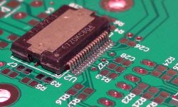
Attached is a photo showing a sample of my hand soldering.
I wil post an updated parts list when I make changes to my current BOM. Don't worry, there weren't any drastic changes.
Attached is a photo showing a sample of my hand soldering.
Attachments
- Status
- Not open for further replies.
- Home
- Amplifiers
- Class D
- Texas Instruments TAS5261