mp8 said:The 3.3 Ohm resistor serves a special purpose. It helps to keep the device operating smoothly at high power levels (Kim may not be the only TI employee lurking around).
In general the best practice for these amplifiers is as Kim stated, one large ground plane.
mp8 - You work for super-mega corp too?! Big brother is watching us... 😉
Seriously, the only purpose for ground lift resistors is to keep a clean ground (signal) clean when connecting it to a dirty ground (power). I'd rather keep the ground plane clean in the first place to avoid using a ground lift resistor all together. These chips are analog after all. The TI front ends are digital (PCM to PWM) and grounding directly to the ground plane will certainly be more beneficial for those parts.
pinkmouse said:It may just be my analogue heritage, but I find that phrase very uncomfortable! 😉
😀 You need to hang around the class d forum more often!
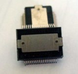
Also, can one of you guys tell us if the heat slug is electrically connected to anything? I don't remember seeing that info out of the many times I've read through the pdf documents.
The heatsink/heatslug should be grounded for best operation.
Going back to the ground resistor. From a ground perspective (both inside and outside the chip) this device runs cleaner with a single ground plane in MOST circumstances. The addition of the 3.3 Ohm resistor does break up the 'noisy' ground from the clean ground, but even if the outputs are switching the power grounds are not the nodes we are protecting against. Removing this resistor, no matter how clean the ground is, can cause problems at high output powers.
Going back to the ground resistor. From a ground perspective (both inside and outside the chip) this device runs cleaner with a single ground plane in MOST circumstances. The addition of the 3.3 Ohm resistor does break up the 'noisy' ground from the clean ground, but even if the outputs are switching the power grounds are not the nodes we are protecting against. Removing this resistor, no matter how clean the ground is, can cause problems at high output powers.
mp8 said:The heatsink/heatslug should be grounded for best operation.
Going back to the ground resistor. From a ground perspective (both inside and outside the chip) this device runs cleaner with a single ground plane in MOST circumstances. The addition of the 3.3 Ohm resistor does break up the 'noisy' ground from the clean ground, but even if the outputs are switching the power grounds are not the nodes we are protecting against. Removing this resistor, no matter how clean the ground is, can cause problems at high output powers.
So if the heatsink should be grounded, that means it is not electrically connected to anything internally, correct? I just want to know because I don't want to connect the heatsink to analog ground if the heat slug is connected to power ground...
If the power grounds aren't the reason for the ground resistor then pins 8 and 16 must be the culprits - they're labeled as power ground pins. What circuitry do they serve as the return path for (referring to the block diagram on page 6 of the TAS5261 datasheet)?
Excellent. Looks like you'll be getting going sooner than I, still once I get my active system up and running then I can get on it. I'm going to use chipamps so I should be done this weekend unless something blows up!
Did you put in a request with a personal address or a business address? My experience is that they will almost always honor your request if the shipping address is a valid business. I've only had a little luck with personal requests. Speaking of samples, I should have 4 TPA2001D1 delivered to work on Monday and hopefully two more TAS5261s when they get some more in stock 😉
My girlfriend is working today so I have time to sit back, drink some beer, finish up the schematic and board, and work on a bill of materials for this project.
My girlfriend is working today so I have time to sit back, drink some beer, finish up the schematic and board, and work on a bill of materials for this project.
My girlfriend is working today so I have time to sit back, drink some beer, finish up the schematic and board, and work on a bill of materials for this project.
In that particular order
 !
!May I advice to move the "drink some beer" part towards the end of your to do list 😀
Regarding the samples: I used the company address I work for.
Regards
I had the beer in my hand while I was typing that, so there's no tunring back now  The beer I'm having is particularly strong (8% ABV) but I'm good for at least a few before I start confusing resistors and capacitors and misspelling words 😉
If you used your company address then I'm sure you'll get samples. TI is nice like that.
The beer I'm having is particularly strong (8% ABV) but I'm good for at least a few before I start confusing resistors and capacitors and misspelling words 😉If you used your company address then I'm sure you'll get samples. TI is nice like that.
Attachments

Now that the weekend and the booze are all gone it's time for an update. The layout is almost done. I still need to connect pins 8 and 16 to power ground at one place and have an idea of how I want to accomplish that without moving too much around. The other things that need to be done are routing some of the traces for the reset and protection connections.
I do have a couple questions regarding the reset, SD, and OTW pins for mp8 and/or kims if they'd be able to help us out. I wanted to use a switch to be able to control the reset pin, so the reset pin would be connected to 3.3V through a pullup resistor and to ground through a switch. When the switch is closed, reset is grounded and the chip goes into reset state. When the switch is open, reset is pulled high and the chip is operational.
*Is it ok to use the Vreg pin as the 3.3V source for the pullup resistor?
Since OTW and SD and active open drain ouputs, I was hoping it would be ok to connect both OTW and SD directly to the reset pin so that the chip would be forced into reset mode if a fault occured.
*Is it ok to tie OTW and SD directly to the reset pin?
I also tidied up the silk screen layers and started working on gathering basic specs for the components. I have a pretty good idea of what I want to use for most of the parts so that shouldn't be too tedious.
The attached image of the board is with both layers turned on, so it's a little difficult to see the details but you get the idea. I'll post the schematic for this layout once I figure out what to do with the reset and protection connections.
Attachments
Wow I want try this beer, it looks very diferent ! 8% of Alcohol ? For god ! Here the beers have between 3 and 5 % of alcohol... 
Many congratulations for the board and the care about "do it right" and in the best way. I'm sure your design will be very optimized.
I've already ordered my chips, I'm anxious to have it working in my bench ! 😎
Cheers !
Many congratulations for the board and the care about "do it right" and in the best way. I'm sure your design will be very optimized.
I've already ordered my chips, I'm anxious to have it working in my bench ! 😎
Cheers !
Thanks nando. The design is as optimized as I can make it for a first try without knowing all the details about the chip that I'd like to.
That beer is only available locally, and it is very good. Very hoppy though. There are beers out there with even higher ABV, but they are usually pretty darn expensive. Being local, this stuff is $28 for a case of 24 12oz. bottles. The best is when you get a fresh case though 🙂
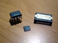
Anyway, the TPA2001D1 samples arrived and boy are they tiny little fellas! They're the same size body as an SO8 package but with 8 pins per side instead of 4. I would imagine some will have trouble soldering this guy. When we get to that stage I can solder that part on for people if necessary.
That beer is only available locally, and it is very good. Very hoppy though. There are beers out there with even higher ABV, but they are usually pretty darn expensive. Being local, this stuff is $28 for a case of 24 12oz. bottles. The best is when you get a fresh case though 🙂
Anyway, the TPA2001D1 samples arrived and boy are they tiny little fellas! They're the same size body as an SO8 package but with 8 pins per side instead of 4. I would imagine some will have trouble soldering this guy. When we get to that stage I can solder that part on for people if necessary.
Attachments
Solder these parts isn't that difficult, but REMOVE it from PCB without damage the device is impossible to me ! 
I'd like to try this beer ! When I buy the PCB from you, maybe you can send it with the PCB and I can send to you some beer from here !
I'd like to try this beer ! When I buy the PCB from you, maybe you can send it with the PCB and I can send to you some beer from here !
-_nando-_ said:I'd like to try this beer ! When I buy the PCB from you, maybe you can send it with the PCB and I can send to you some beer from here !
I'll look into it, but I don't think it would be cheap (or even legal) to ship beer outside the country!
Another update: I received the order from CWS today, but they only shipped me two of each core and I had ordered 4 of each type of core. Now I have to wait to see how they reply to my email. The packing slip even has the correct quantities on it... Makes me a little wary of ordering from them again for screwing up such a simple order. I wouldn't mind so much but those MPP cores are $3 a piece! The Sendust were $1.50 a piece so, they forgot to ship me $9 worth of parts out of a $30 (including shipping) order...

As I mentioned earlier I applied for some free samples. To my big surprise two TPA2001D1 are already on there way and two TAS5261 are planned to ship the 2nd of next month! 🙂
Regards
Regards
BWRX, do you have some sort of preliminary BOM already? Just to get an idea what I would need.
Regards
Regards
Yes, but it doesn't have all the info you need. So I guess that would technically mean no 🙂 Look for the components around the TAS5261 on the TAS5261 eval board BOM and you'll get some idea of what you'll need. Look at the TPA2001D1 or TPA2000D1 eval board BOM and you can find some more components you will need if you plan to use that part of the circuit. Of course I've used components that aren't on those BOMs, but you'll see one from me soon enough.
I should have some time later tonight to work on that since the board is done except for the SD, OTW, and reset connections. Maybe I should send an email to mp8 and kims since TI has not replied to my email asking the questions from one of my previous posts.
I should have some time later tonight to work on that since the board is done except for the SD, OTW, and reset connections. Maybe I should send an email to mp8 and kims since TI has not replied to my email asking the questions from one of my previous posts.
I got tired of waiting and connected things as I saw fit. Jumpers/resistors can be left out if the sd, otw, reset connections don't work. They're not that big of a deal anyway.
As promised, here is the schematic. I will make sure I have the correct information for all the parts before exporting and uploading the parts list.
As promised, here is the schematic. I will make sure I have the correct information for all the parts before exporting and uploading the parts list.
Attachments
- Status
- Not open for further replies.
- Home
- Amplifiers
- Class D
- Texas Instruments TAS5261