Snap!
I'm sitting at my PC, and inbetween job hunting I'm starting to convert Brian's schematic to through hole components. I'm looking at 12mm spacing for the resistors, a compromise between size and general availablity, and MJE15030s for the regs. Apart from the input caps, where I will allow for the option of bigger ones, I'm thinking 5mm pin spaciing for all the film caps.
I'm sitting at my PC, and inbetween job hunting I'm starting to convert Brian's schematic to through hole components. I'm looking at 12mm spacing for the resistors, a compromise between size and general availablity, and MJE15030s for the regs. Apart from the input caps, where I will allow for the option of bigger ones, I'm thinking 5mm pin spaciing for all the film caps.
Al, 12mm spacing for the resistors is pretty large and will take up a lot of room. I would go with a smaller spacing if possible. I made packages for the output filter caps so that either 5mm or 7.5mm lead spacing types could be used. I plan on using 5mm lead spacing polyester film types initially.
The transistors that regulate the 12V gate supplies should have a reasonably high DC current gain (~100) and a minimum Vce rating of 60V. If you choose a transistor with a lower gain I would lower the value of R11 and R12 to allow more current to bias the zener. Be careful of the power dissipation in R11 and R12 if you lower their resistance.
Also, you could use either a 12V or 13V zener. I would probably choose to use a 13V zener, but wrote 12V in on the schematic.
Hi Brian
12mm for the resistors seems to be a good compromise, it allows most 1/2 and 1/4 W through hole resistors to be used. Yes, the size of the board will be compromised, but I'm good at compact designs, and this supposed to be a little different to yours! 😉
I misread the datasheet for the gate supplies, now I've checked, I've seen they need a lot less current than I originally assumed, so something like an BC546B or C should work well, unless you know better of course!
12mm is a good compromise, but the majority of the resistors need only be 1/8W or lower. Anything larger is just eating up a lot of space and could compromise the position of other important components.
You're right that the gate supplies don't need much current at all. I over engineered them on purpose because the draw from those supplies will be pulsed current at the rate of the switching frequency. You can certainly get away with lower current transistors. You can put a resistor in series with the collector to shift some of the dissipation away from the transistor as well. A TO220 transistor would easily be able to handle the dissipation.
You're right that the gate supplies don't need much current at all. I over engineered them on purpose because the draw from those supplies will be pulsed current at the rate of the switching frequency. You can certainly get away with lower current transistors. You can put a resistor in series with the collector to shift some of the dissipation away from the transistor as well. A TO220 transistor would easily be able to handle the dissipation.
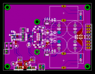
After reading the data sheet one more time... I've decided that it would probably be best to just leave the OTW and SD pins disconnected. The reset pin will still be connected to 3.3V through a resistor and to ground through a switch so the reset function can be toggled by the user. Other than that, my layout is finished.
The next question is, who wants this board and how many would you like?
The next question is, who wants this board and how many would you like?
Attachments
What I understand is that OTW and SD would be connected to a microcontroller to make further operations, other than RESET, in case of errors: turn down volume, send a message to a display, light leds.... We can survive without.
I'd like to have 4 boards.
I wait for instructions about external component. In a couple of weeks I'll receave the TI chips. 🙂
Ciao
Thomas
I'd like to have 4 boards.
I wait for instructions about external component. In a couple of weeks I'll receave the TI chips. 🙂
Ciao
Thomas
Since TI was so kind to send me samples of the chips I feel obligated to by at least two boards 🙂
Regards
Regards
Well, I'm in for at least 4 boards 😉
Another interesting front end modulator to experiment with uses two 555 timers; one produces a clock signal and the other modulates the signal. You can see an example of how to get a PWM signal from a 555 timer on page 13 of TI's 555 timer datasheet: http://focus.ti.com/lit/ds/symlink/ne555.pdf
I will try that as a front end too, since I have a bunch of timer chips.
Hey guys. CWS is correcting their mistake and sending me the cores they forgot to ship so I figure I can trust them now. Would anyone like me to order T106 sized cores and wire for them? I'll be putting in another order and can do a little group buy if anyone is interested. The MPP cores are $3 each and the Sendust cores are $1.50 each. 16 gauge wire is $0.18 per foot and 18 gauge wire is $0.16 per foot. Post here and/or send me an email through the forum if you're interested.
Would anyone like me to order T106 sized cores and wire for them? I'll be putting in another order and can do a little group buy if anyone is interested. The MPP cores are $3 each and the Sendust cores are $1.50 each. 16 gauge wire is $0.18 per foot and 18 gauge wire is $0.16 per foot.
Fine for me. You can choose whatever is best.
Regards
My parts list is almost finished and I will finalize it and post it later today. Depending on what parts you pick I would wager that the cost for parts per board would be around $40-50 (assuming prices similar to those of the major parts suppliers). This does not include the cost of the PCB or the TI chips, the TAS5261 of which you wold need to get samples of at the moment (I was told they're currently on backorder too). If my tally is correct, there are a total of 89 parts per board.
I will see how much a double sided silk screen would add to the cost of the boards. I'm expecting each board to be roughly $10-15 with only one side silk screened.
Tallying up all costs, and conservatively rounding up, it looks like the raw cost for a pair of boards and parts will be about $120. You will also need a couple low current 15VDC ~500mA or so wallwarts and a high current 50VDC max supply. A transformer with dual 33VAC secondaries would be good for this application.
Some type of heatsink will also be needed for the TAS5261s. Some type of CPU heatsink would work well if you can't find anything else.
Hi Brian,
A big doubt raised to me reading around about TI Equibit Tech without feedback: TAS5261 is such a kind of amp?
Here is a thread with KIM from TI.
http://www.diyaudio.com/forums/showthread.php?postid=915335#post915335
KIM's and John Hope's answer is that a very precise SMPS is required and designed as a whole system with AMP. KIM attached this reference design from TI
http://focus.ti.com/lit/an/slea038/slea038.pdf
After this, if you confirm, we can forget standard PS for TA5261, or we get 10% THD.
A big doubt raised to me reading around about TI Equibit Tech without feedback: TAS5261 is such a kind of amp?
Here is a thread with KIM from TI.
http://www.diyaudio.com/forums/showthread.php?postid=915335#post915335
Eva said:Open loop digital systems are a big no-no, a stupid dead-end
Lars Clausen said:
But i suspect the open loop amplifier would require incredible precision from the power supply rails under load condition.
For example if you are working with a 100W amplifier you would use a rail voltage of say 60 Volts per rail.
Now just 10 mV of rail change on the supplies will add 0.02% of THD. This is 10 times the total THD level on the currently best Class D amplifiers.
John Hope: can you really keep this kind of precision, and stability, in real life?
KIM's and John Hope's answer is that a very precise SMPS is required and designed as a whole system with AMP. KIM attached this reference design from TI
http://focus.ti.com/lit/an/slea038/slea038.pdf
After this, if you confirm, we can forget standard PS for TA5261, or we get 10% THD.
thomaseliot said:A big doubt raised to me reading around about TI Equibit Tech without feedback: TAS5261 is such a kind of amp?
Hi Thomas. The TAS5261 does not have feedback and will require a reasonably stiff power supply to sound good. I would imagine a standard transformer, rectifier, high capacitance supply will be adequate for most people. There is quite a bit of capacitance on the PCB, but any supply rail filtering prior to the PCB will be beneficial.
Doubts confirmed then. The problem is that without feedback any variation in the PS will be present to amp output. An unregulated PS will never have a stability in the range of milliVolts.
Any hope to build something like the TI smps reference design?
Any hope to build something like the TI smps reference design?
I'm not going tackle a synchronous buck regulator as I already have a 33VAC transformer, bridge rectifiers, and large filter caps from a previous project to use. You can certainly source a SMPS to power this though. Keep in mind that you can use a maximum supply rail voltage of 50V. You can use lower than that but the maximum power output will decrease.
An alternative would be to use a front end that can accept pre or post filter feedback. There's also nothing stopping anyone from designing a TI based front end either 😉
That hasn't stopped the low power Tripath amps from sounding good.
An alternative would be to use a front end that can accept pre or post filter feedback. There's also nothing stopping anyone from designing a TI based front end either 😉
thomaseliot said:The problem is that without feedback any variation in the PS will be present to amp output. An unregulated PS will never have a stability in the range of milliVolts.
That hasn't stopped the low power Tripath amps from sounding good.
Tripath amps have all feedback before output filter.
With Equibit amps there is no feedback, even with TI front ends.
I'm not able to build an smps but, without, has it still a sense to build an amp that will not sound as it was designed for? With unregulated PS we are going to have 10% thd.
With Equibit amps there is no feedback, even with TI front ends.
I'm not able to build an smps but, without, has it still a sense to build an amp that will not sound as it was designed for? With unregulated PS we are going to have 10% thd.
thomaseliot said:Tripath amps have all feedback before output filter.
Are you sure? I know the higher power ones do, but I've never seen this indicated in the datasheets of the lower power chips like that TA2020, 2021B, and 2024.
The gain on those is set by two external resistors that are part of the input stage feedback only.
thomaseliot said:I'm not able to build an smps but, without, has it still a sense to build an amp that will not sound as it was designed for? With unregulated PS we are going to have 10% thd.
I plan on using the TPA2001D1 for evaluation purposes only and hope to come up with a better front end if the output stage performs well. That was the whole reason for providing connections for external PWM inputs 🙂
- Status
- Not open for further replies.
- Home
- Amplifiers
- Class D
- Texas Instruments TAS5261