Hello baudouin0,
As you recommended I change the value of C15 into 390pF (I don't have 330pF value).
Then I installed three terminal with elements' value as you presented on your schematic.
There was some improvement as the circuit started to be more resistant to generate LF resonances. Still I cen see them arriving but after few seconds with the constant sinus signal below 10 Hz. I used as C9 = 680uF cap but I can increase its value easily.
I also did the experiment decreasing the values of C33,34 from 0,68uF to 0,22uF but it doesn't worked.
In a free time I will check the influence of modification on the sound of the music.
Thanks a lot , Jarek
Yep I tried C33,C34 but made it worse on simulation. You may also need to stabilize V4 as any mains voltage changes will get in here. Maybe a shunt zener.
Why are C3 and C4 so large? A tenth of that value would still be very large.
All good fortune,
Chris
All good fortune,
Chris
I enclose the sheet in Excel which which explanes some relation between Vout and phase vs frequency. Output signal is measure by the scope and Sanwa multimeter. Phase readouts are from the scope. Input signal is from he generator. Measurements are done generaly for 6Volts RMS. As I understand you also wanted to see Lissayous curve to check the phase relations of input output signals. I will do some photoes and send them.Even an X-Y scope display can be used to view magnitude and phase if your meters don't have good response below 10Hz.
Yes the situation in Ukraine is tough and dangereous for the people. Unfortunately Poland is situated in the middle of the conflict.
<trobbins>
Even an X-Y scope display can be used to view magnitude and phase if your meters don't have good response below 10Hz.>
OK I will send you some photos from scope display frequences and voltage amplitude being in interest.
Even an X-Y scope display can be used to view magnitude and phase if your meters don't have good response below 10Hz.>
OK I will send you some photos from scope display frequences and voltage amplitude being in interest.
Just ideas you may have done some of these. HPF on input. Zener supply (use 150V zener if you can get one) for first stage. Altered bias on first stage as plate voltage getting a bit low.
Hello baudouin0,
So your suggestion is to replace the second voltage regulator by simple Zener diode stabilization? No problem. I will test the solution.
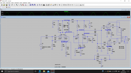
Let me explain - both voltage regulator are practically based on the same schematic and differ only by Zener diodes implemented. If necessary can list the schematic.
Other thing I was thinking about are the PSU chokes ( not on the listed amplifier section). Chokes are 10H connected directly to anode fuses each channel and may cause some resonances in the amp. Will test it replacing them by resistors.
Thanks, Jarek
So your suggestion is to replace the second voltage regulator by simple Zener diode stabilization? No problem. I will test the solution.
Let me explain - both voltage regulator are practically based on the same schematic and differ only by Zener diodes implemented. If necessary can list the schematic.
Other thing I was thinking about are the PSU chokes ( not on the listed amplifier section). Chokes are 10H connected directly to anode fuses each channel and may cause some resonances in the amp. Will test it replacing them by resistors.
Thanks, Jarek
You need to calculate the resonance of the CLC Pi filter and make sure it is well under 100 or 120Hz, by several octaves. Otherwise it can actually be helping the hum, not harming it.
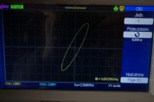
With respect to the spreadsheet results in post #470 - I think the scope V measurement for 200Hz is 6.08V (not 5.08V) ?
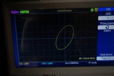
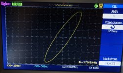
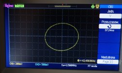
An X-Y plot of output to input voltage should clearly identify when phase passes through 90 deg as frequency is reduced towards 10Hz (vertical line/ellipse - see attached diagram). I'd suggest that there is not enough closed loop gain drop as 10Hz is approached (ie. only -1.6dB at 15Hz), and your OPT is starting to cause substantial phase shift to the point of reaching 180 deg well before loop gain has fallen through 1 (ie. unstable conditions). My view is that if you want to still use that OPT then LF gain needs to be rolled off aggressively, and likely starting at a frequency in the audio range (perhaps 50-150Hz) depending on the mid-band feedback level, The use of a large 680nF value for C3/C4 has exacerbated the LF instability, as C3/C4 now doesn't cause much roll-off in gain at 10Hz. As a simple change (and indicator) you could keep reducing the value of C3/C4 till you achieve stable operation. A shelf network as part of C3,C4 may then give you a compromise solution.
What you are experiencing is similar to many amps that want to include global feedback around an OPT.
Attachments

Hello trobbins,
I will do photos of XY diagrams at low frequency (limit by my generator to 10Hz).
Then I also prepare photos HF because I want to have your opinion about it.
The replacement of brand name Hamond OPT is rather out of question.
Regards,
Jarek
I will do photos of XY diagrams at low frequency (limit by my generator to 10Hz).
Then I also prepare photos HF because I want to have your opinion about it.
The replacement of brand name Hamond OPT is rather out of question.
Regards,
Jarek
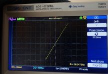
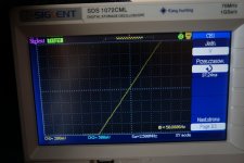
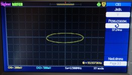
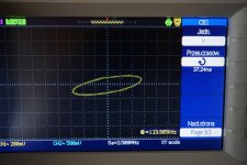
I list photos with XY curves for certain frequences.
For curve <10Hz resonance appears after few seconds. The bigger signal amplitude the sooner.
Regards, Jarek
For curve <10Hz resonance appears after few seconds. The bigger signal amplitude the sooner.
Regards, Jarek
Attachments
-
 DSC01260_25,44 Hz_comp.jpg246.6 KB · Views: 73
 -
 DSC01260_29,641 Hz_comp.jpg199.2 KB · Views: 74
 -
 DSC01260_50,8806Hz_comp.jpg205.3 KB · Views: 70
 -
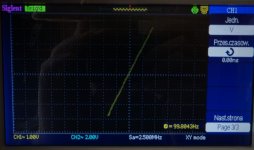 DSC01260_99,884Hz_comp.jpg160.1 KB · Views: 90
 -
 DSC01260_99,88356 Hz_comp.jpg163.2 KB · Views: 65
 -
 DSC01260_989,236 Hz_comp.jpg221.5 KB · Views: 78
 -
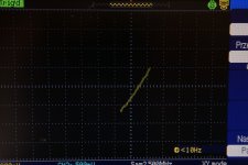 DSC01271_less10Hz_comp.jpg216.2 KB · Views: 67
 -
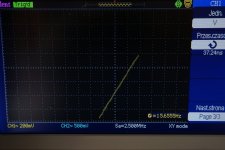 DSC01273_15,6555Hz_comp.jpg243.1 KB · Views: 74
 -
 DSC01274_20,54Hz_comp.jpg258 KB · Views: 73
 -
 DSC01277_50,88Hz_comp.jpg226.9 KB · Views: 74
 -
 DSC01278_Mullard_comp.jpg486.7 KB · Views: 70
 -
 DSC01279_9,786kHz_comp.jpg314.1 KB · Views: 74
 -
 DSC01280_42,45kHz_comp.jpg264.9 KB · Views: 68
 -
 DSC01282_94kHz_comp.jpg261.4 KB · Views: 69
 -
 DSC01283_103kHz_comp.jpg267.3 KB · Views: 68
 -
 DSC01284_124kHz_comp.jpg244.3 KB · Views: 67
Instability at low frequencies that begins with a larger signal demand is classically caused by either an under-isolated power supply (insufficient decoupling) or by a shifting of a low frequency pole. Yours doesn't seem to be the first of these, and few modern designs would be - bypass capacitors are cheap these days.
The second possibility is that you're running a very long feedback loop over several low frequency poles and not being aware of all potential issues. If you're depending on the output transformer's (OPT) primary inductance to form the dominant pole with the output valves' source impedance, you'll have two signal level dependent variables, not ideal.
OPT primary (magnetizing) inductance varies with signal level, and in the wrong direction. As signal level increases, so does primary inductance, which shifts that pole downwards in frequency, closer to the RC poles. Not good. This pole cannot be relied on as your dominant pole; you need a better one. It's also a poor choice for distortion and overload recovery time, but those are separate issues.
If you absolutely must, for whatever reason, use a long loop feedback, choose an RC dominant pole somewhere. OPTs are wishy-washy and will only break your heart in the end.
All good fortune,
Chris
Jarek, what is the dB level of mid-band feedback being applied? With feedback applied, the LF phase shift is likely to be negligible until OPT roll off kicks in, which appears to be why your LF plots show little phase change given you only go down to 10Hz. I should have advised to do LF testing with feedback disconnected. I'd also suggest that an oscillator that goes down to 1Hz is needed to better appreciate what is happening, as well as to use a lower input signal so that LF resonance is not entered, and then the response may be easier to plot/identify.
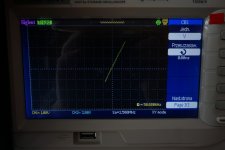
The HF phase photos indicate that phase rises to 90 deg by 40kHz, but doesn't wander much away from 90 deg till after 100kHz. A squarewave response may be more enlightening of any dominate resonances that could influence stability.
The HF phase photos indicate that phase rises to 90 deg by 40kHz, but doesn't wander much away from 90 deg till after 100kHz. A squarewave response may be more enlightening of any dominate resonances that could influence stability.
Could you post you power supply schematic please. I would not expect this design to be unstable at 10Hz. If there's a problem in the amp it would be about 1Hz.
Yes, the 145V and 320V regulators may be a concern. In the Williamson amp, resistor droppers are used with 8uF filter caps for the supply rails to the input stage and PI stage, but few seem to appreciate that those RC circuits were designed with filter corner frequencies to provide some additional phase margin for LF stability. So many people cloning the Williamson just increase the 8uF as a naive way to 'improve' performance, only to end up degrading phase margin. I'm not sure if the RC filtering for the 5-20 has a similar affect, but if they did then the 145V and 320V regulators may be a concern apart from having their own quirky LF response.
Last edited:
- Home
- Amplifiers
- Tubes / Valves
- Testing newly built mullard 5-20