I can see a spec for a 1650H for 4x245H across the whole winding at 60Hz. The HA is quoted at 1KHz which is where the primary cap will kick in so that's no good. That will make the break frequency very low. So CH suggestion C33, C34 to make dominate pole with 47-100nF sounds like a way forward, C14 I would keep large say 470uF so this is very low too. We can simulate your design if required I have a model of 1650T (measured) and 1650R just a matter of changing the parameters. As you can see from the comments there is different advise. This is because without analyzing the actual circuit its difficult to know.
Last edited:
Your circuit is fine, should just need tweaking a bit, though a paralleled ECC83 on the front end is very high gain, but there's not much you can do about it now without making many changes as your direct coupled to the PS.
For what it's worth I built an amp with the Hammond 1650TA, I also had LF stability issues solved in part by cleaning up the layout, moving the odd ground and using a shelving network.
Andy.
For what it's worth I built an amp with the Hammond 1650TA, I also had LF stability issues solved in part by cleaning up the layout, moving the odd ground and using a shelving network.
Agree there,though I'm more one for testing the actual amp than simulations.without analyzing the actual circuit its difficult to know.
Andy.
I would think that switching SW1 from the 6SN7 to the ECC99 would leave the grids of the 6SN7 floating. As far as I know, this is not good (a repetative process of the grids charging up and discharging again could occur).
I would also think that witching SW1 from the ECC99 to the 6SN7 will give a 'pop' or something like that in the speakers.
I would also think that witching SW1 from the ECC99 to the 6SN7 will give a 'pop' or something like that in the speakers.
Last edited:
OK simulated your design both LF and HF marginally stable.
For LF C33,C34 = 100nF, C14 = 470uF. Connect R46,C46 to cathode of V1 (positive end of C14) rather than negative end of C14
For HF consider fitting dominant pole 10k+470pf across R13. Increase C46 to 680pF. Will need testing with transformer.
For LF C33,C34 = 100nF, C14 = 470uF. Connect R46,C46 to cathode of V1 (positive end of C14) rather than negative end of C14
For HF consider fitting dominant pole 10k+470pf across R13. Increase C46 to 680pF. Will need testing with transformer.
Attachments
Last edited:
So, changing C33/C34 to 100nf lifts LF response and increasing C14 to 470u lowers the response at V1. Why increase C14 value? Also what does moving the NFB from negative end of C14 to cathode of V1 do please? I'm not doubting your calculations but as I'm no expert only trying to understand and learn.For LF C33,C34 = 100nF, C14 = 470uF. Connect R46,C46 to cathode of V1 (positive end of C14) rather than negative end of C14
Andy.
.png") This is the best solution I can find. Note C33 and C34 are now 1uF and the pole zero cancellation is done with C14. I have reduced the NFB down to about 20dB.
This is the best solution I can find. Note C33 and C34 are now 1uF and the pole zero cancellation is done with C14. I have reduced the NFB down to about 20dB.Thanks for your effords baudoin0 and the time spent to prepare new schematic for me. After my holidays I will test your proposition and let you know about the results achieved,
Greetings,
Jarek
Greetings,
Jarek
Best just to build from simulation - don't mix and match. If that does not work come back to us. Loop stability can sometimes be counter intuitive. As a rough explanation the reason for taking the NFB back to the top of C14 is that you don't want C14 acting as another coupling cap in the system that just pushes the lag even further. Hope this helps -its a Sowter UA21 OPT but is very similar to the 1650H.
Best just to build from simulation - don't mix and match. If that does not work come back to us. Loop stability can sometimes be counter intuitive. As a rough explanation the reason for taking the NFB back to the top of C14 is that you don't want C14 acting as another coupling cap in the system that just pushes the lag even further. Hope this helps -its a Sowter UA21 OPT but is very similar to the 1650H.
Hello Baudouin0,
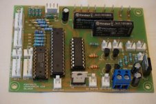
I'm back again. I have prepared new PCB regulators for 320V and 145V and new uPcontroller for the amp. See enclosed photos.
On weekend I will try to modified the amp schematic according to your suggestions.
Regards, Jarek
Attachments

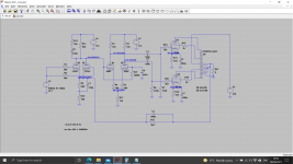
I'm back with you again. I enclosed the real schematic according to which I modified my EL34 amplifier.
The amp don't have any parasitic oscillations (about 1Hz) now. It's a big relief well as good lesson for me.
The oscillations desappeared when I did the changes but only in two channels simultaneously.
Shown measurements results on the schematic were reached after 15minutes of amp work. Mains voltage was 234V AC. Maximum acoustic power RMS is 25W/4Ohms at1kHz. Next planned activities are:
- testing when decreasing of C33/C34 capacitor values.
- obtaining plate current values inV2 tube in the range of optimum for 6SN7 3-3,5mA and replacing cathode resistor by FETs CCS
- preparing PCBs for switching from distributed load to triode mode.
Attachments
A couple of questions where does out X-X and out Y-Y go? I also notice there's no grid bias on the headphone part of your amp - the grids appear to be floating as far as DC is concerned or does X-X and Y-Y out go somewhere. JFET CCS do require adjustment as the threshold voltages can be variable.
Something I do with cathode bias is to replace some of it with a zener. So R46 and R43 both become a 5W zener and a resistor in series. You might soak up say 65% of the voltage with the zener. The idea is that on big signals when the stages go into class B the current goes up and the static bias down increasing the crossover distortion to the point it can become audible. The resistor is still needed to stabilize the EL34 tolerance and prevent thermal runaway.
Something I do with cathode bias is to replace some of it with a zener. So R46 and R43 both become a 5W zener and a resistor in series. You might soak up say 65% of the voltage with the zener. The idea is that on big signals when the stages go into class B the current goes up and the static bias down increasing the crossover distortion to the point it can become audible. The resistor is still needed to stabilize the EL34 tolerance and prevent thermal runaway.
Some measurements are presented in a box and others aren't ?
There are some labels 'X-X' ?
What is the feedback level being applied?
Are 0V and 0(350V) and COM and the ground symbol all the same level and connected? Perhaps they are distributed groups that star together?
Fusing a 430Vdc feed to an OPT is not a good idea imho.
The '41%' label needs a note that it refers to turns ratio and not impedance (as the secondary windings refer specifically to impedance).
The 1650HA has quite a low PP inductance, which is the dominant contributor to forward path LF drop-off, given the CR networks and the RC networks now have corner frequencies below 1Hz and likely far enough below the OPT corner to not cause sufficient phase shift for unstable feedback operation (although all those CR and RC networks have closely spaced corner frequencies).
V3 has no grid DC reference and V2's DC reference depends on switch position. Operating that switch live will be memorable for the speakers.
Dominant LF poles made with the output transformers' inductance are tricky - inductance varies dramatically with signal level, and in the wrong direction. Beware, brother, beware.
All good fortune,
Chris
Dominant LF poles made with the output transformers' inductance are tricky - inductance varies dramatically with signal level, and in the wrong direction. Beware, brother, beware.
All good fortune,
Chris
Fusing the HT to the OPT is OK providing the fuse has the correct DC rating and you put a catch (reverse biased) diode from the output of the fuse to ground. Without it the current tries to continue to flow and the HT goes a few KV negative. I used this method on several amps and it does limit the damage if an output valve goes short.
Last edited:
The 1650HA has quite a low PP inductance, which is the dominant contributor to forward path LF drop-off, given the CR networks and the RC networks now have corner frequencies below 1Hz and likely far enough below the OPT corner to not cause sufficient phase shift for unstable feedback operation (although all those CR and RC networks have closely spaced corner frequencies).
I saw two different figures for primary inductance one at 50Hz and one at 1KHz. The 1KHz is much lower due to the primary capacitance.
The datasheet link in post #429 shows a PP inductance at 1kHz and 1V of 11H. It does seems bizarre that Hammond chose 1kHz for that parameter, as it is normally measured at 50/60 Hz due to the self-resonance often occurring about 1kHz. Maybe its a typo error. Also the 1V excitation level is quite low for a comparative level to other OPT's. Maybe they spent their dollars on the HP4192a, which only goes up to 1.1V excitation, and they are reading out the equivalent parameters at 1kHz and believing them. I can't identify another 1650HA datasheet with a 50Hz inductance measurement.
Finding a DC rated fuse at 430V and with such a large inductive load is a hard ask for anyone I'd suggest. Hopefully the power transformer secondary HT winding is fused and with a fuse rating that provides appropriate discrimination.
Finding a DC rated fuse at 430V and with such a large inductive load is a hard ask for anyone I'd suggest. Hopefully the power transformer secondary HT winding is fused and with a fuse rating that provides appropriate discrimination.
><A couple of questions where does out X-X and out Y-Y go?>
See dotted rectangle on the schematic. It serves to elevate filament voltage from cathode potencial about 40VDC.
<I also notice there's no grid bias on the headphone part of your amp - the grids appear to be floating as far as DC is concerned or does X-X and Y-Y out go somewhere.>
Issues with the headphones will be straighten later on.
<JFET CCS do require adjustment as the threshold voltages can be variable.> I am aware of the problem. CCS need always some adjustment and DN2540N5(N3) will need selection.
<Something I do with cathode bias is to replace some of it with a zener. So R46 and R43 both become a 5W zener and a resistor in series. You might soak up say 65% of the voltage with the zener.>
Let me do some approximate calculation for total voltage drop equal 30VDC: for Zener diode -20V (1N5357B 5W on shelf) and 10VDC for the resistor, for quiescence point current 0,07A resistance is about 150R continuous power below 1W so 5W rating is OK.
<The idea is that on big signals when the stages go into class B the current goes up and the static bias down increasing the crossover distortion to the point it can become audible. The resistor is still needed to stabilize the EL34 tolerance and prevent thermal runaway.
OK we will see after experiments.
Jarek
><Some measurements are presented in a box and others aren't ?>
Correct. In the frame are values for the L chanel, and without for the Right one.
<There are some labels 'X-X' ?>
Levels of elevation of the filament values.
What is the feedback level being applied?
<Are 0V and 0(350V) and COM and the ground symbol all the same level and connected? Perhaps they are distributed groups that star together?>
Wiring is done first in the lokal group connected with the certain tube GRN1, GND 2. Then the groups are connected with the central Ground Point. See it at the center of the photo enclosed.
Fusing a 430Vdc feed to an OPT is not a good idea imho.
The '41%' label needs a note that it refers to turns ratio and not impedance (as the secondary windings refer specifically to impedance).
<The 1650HA has quite a low PP inductance, which is the dominant contributor to forward path LF drop-off, given the CR networks and the RC networks now have corner frequencies below 1Hz and likely far enough below the OPT corner to not cause sufficient phase shift for unstable feedback operation (although all those CR and RC networks have closely spaced corner frequencies).
Jarek
- Home
- Amplifiers
- Tubes / Valves
- Testing newly built mullard 5-20