The 1650H datasheet shows primary brown-red = 245H @ 60Hz. You can fuse OPT as long as you have a reverse protection diode to catch the negative spike and the fuse rating >> HT. I've used 800V or 1KV - and yes I blew one and nothing bad happened. If you prefer a bright glow from the valve and a plume of smoke from the cathode resistor that's OK too. Fusing the secondary main transformer winding will also be inductive - I tend to fuse on the mains input (also inductive) and the OPT HT with the reverse diode.
Last edited:
The 1650H also shows leakage inductance measured at 60Hz - I'm not sure who prepares those datasheets but measuring leakage inductance at 60Hz makes no sense - just as much as not putting in PP inductance at 60Hz in the 1650AH.
A fuse in the OPT B+ feed has to break DC current - the B+ supply is still at some level of DC at the time the fuse starts to melt, and would then increase back to unloaded B+ as the internal arcing begins. The fuse conducts the fault DC up until the fuse somehow stops conducting - that is not a normal AC fuse operating mechanism whereby the AC causes periodic zero current points (and is what the fuse is designed and specified to work with). It's nice to hear that 'nothing bad happened', but that is poor advise to give in a forum imho.
DC fuses have an inductance related capability in the form of L/R. AC fuses don't have such a need for AC applications like the primary or secondary side of transformers - inductance of the power transformer windings are irrelevant.
Last edited:
As long as the DC rating of the fuse is greater than the HT the reverse diode will stop the voltage spike exceeding this. Don't put comments on the forum such as 'but that is poor advise to give in a forum imho'. We agree to disagree.
This is what I used for each channel of the 2x120W amp.
https://www.mouser.co.uk/datasheet/2/240/Littelfuse_Fuse_508_Datasheet.pdf-1317307.pdf
This is what I used for each channel of the 2x120W amp.
https://www.mouser.co.uk/datasheet/2/240/Littelfuse_Fuse_508_Datasheet.pdf-1317307.pdf
Last edited:
315mA is the lowest rating, with a 630mA for 2 min max spec - that's going to be stressful for many an OPT primary winding.
Yep it was on a much bigger amp I used these fuses. I think they have some sort of sand in them. There maybe smaller ones. Usually if the valve goes short quite a big current flows.
Hallo baudouin0,
After a long delay I am back in the action.
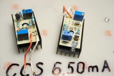
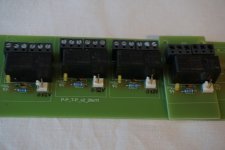
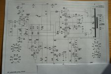
In the meantime I introduce some changes in the schematic of my Mullard amplifier. I replaced cathode resistors in inverting stage with MOSFet CCSs (6,5mA) and introduce the possibility of using the amplifier in Pentode or Triode mode (see the enclosed photos of the hardware). I enclose the actual schematic of the amplifier in pdf format. Phone buffer is temporary disconnected.
I tested the Mullard amplifier listening to the music and I think there are still some issues to be removed. So I went back to generator-scope measurements.
When I went down with the generator below 20Hz on the sinus I can see at the scope the step (shelf) on the curve in which I can see the resonance at higher frequency and after few seconds at the Ampmeters at the front of the case you see a resonance ( high amplitude strikes about 1Hz). Then when I go up with frequency (about 60Hz) the resonance disappear.
Next issue is in the ultrasonic area when I go with the frequency of the sinus up. The roll of frequency (-3dB) is at about 33,5kHz and father the amplitude of the signal lowers and at about 70kHz and you can observe something like the switching of the phase of the signal. Then the amplitude is becoming bigger but about 108kHz goes down again. I think these are the results of resonances of the OPT.
The mentioned above phenomena were achieved with the values of C14=2200uF(electrolitic), C46=690pF (mica) and C33,34=0,68uF(polypropylene).
What other activities can I do to heal the amp?
Best regards, Jarek
After a long delay I am back in the action.
In the meantime I introduce some changes in the schematic of my Mullard amplifier. I replaced cathode resistors in inverting stage with MOSFet CCSs (6,5mA) and introduce the possibility of using the amplifier in Pentode or Triode mode (see the enclosed photos of the hardware). I enclose the actual schematic of the amplifier in pdf format. Phone buffer is temporary disconnected.
I tested the Mullard amplifier listening to the music and I think there are still some issues to be removed. So I went back to generator-scope measurements.
When I went down with the generator below 20Hz on the sinus I can see at the scope the step (shelf) on the curve in which I can see the resonance at higher frequency and after few seconds at the Ampmeters at the front of the case you see a resonance ( high amplitude strikes about 1Hz). Then when I go up with frequency (about 60Hz) the resonance disappear.
Next issue is in the ultrasonic area when I go with the frequency of the sinus up. The roll of frequency (-3dB) is at about 33,5kHz and father the amplitude of the signal lowers and at about 70kHz and you can observe something like the switching of the phase of the signal. Then the amplitude is becoming bigger but about 108kHz goes down again. I think these are the results of resonances of the OPT.
The mentioned above phenomena were achieved with the values of C14=2200uF(electrolitic), C46=690pF (mica) and C33,34=0,68uF(polypropylene).
What other activities can I do to heal the amp?
Best regards, Jarek
Attachments
Jarek, you may want to initially do some squarewave testing in order to verify what high frequency resonances you have, and whether your C46 value is reasonable, You may then want to verify squarewave performance with a range of load conditions to confirm there are no unstable conditions. If you have a stable amp, then you could consider removing R15-C15 and rechecking for stable operation and HF resonances. Apart from C46, there is also another simple means to improve HF compensation.
For low frequency instability, you may want to do a rough plot of gain and phase going down to below 1Hz to identify the peaking characteristic. One way to suppress that resonance is to introduce a step filter with C33 and C34 as first shown by GEC (http://www.tubebooks.org/books/gec_approach.pdf).
For low frequency instability, you may want to do a rough plot of gain and phase going down to below 1Hz to identify the peaking characteristic. One way to suppress that resonance is to introduce a step filter with C33 and C34 as first shown by GEC (http://www.tubebooks.org/books/gec_approach.pdf).
Is it possible that replacing cathode resistor 12kOhm with CCS destabilizate the amplifier?
Jarek
Jarek
Hallo trobbins,
<Jarek, you may want to initially do some squarewave testing in order to verify what high frequency resonances you have, and whether your C46 value is reasonable, You may then want to verify squarewave performance with a range of load conditions to confirm there are no unstable conditions. >
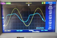
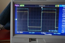
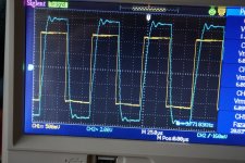
I started with such a test and obtain results as on the photos. Going down with the frequency is still hazardous, as below 20Hz resonance on the Ampermeters appears. When going up –see results on photos. You can observe few sinus periods which diminish to zero. From the photo with 10kHz I estimate their frequency to be between 60-80kHz and the frequency is constant.
<If you have a stable amp, then you could consider removing R15-C15 and rechecking for stable operation and HF resonances. >
So I disconnected R15-C15 two-terminal and the situation was the same as before.
<For low frequency instability, you may want to do a rough plot of gain and phase going down to below 1Hz to identify the peaking characteristic>
I don’t understand. You want me to diagram of Uout vs phase Uin- Uout?
I have read the appointed GEC text about shelf filter. I also found some comments about this phenomena in Morgan Jones book entitled ’Valve amplifiers’. He calls such a circuit ‘step network’.
The values of resistance and capacitance proposed are little bit different there. Also he is of the opinion the circuit should be used before differential stage so before V2 in my schematic –I though it should be installed after C33,C34 so before V3,V4. No precise mathematic explanation of the R,C how they depend on primary OPT inductance.
So I will prepare some electronic elements and start the test with shelf filters. I will be back with the results.
Best regards, Jarek
<Jarek, you may want to initially do some squarewave testing in order to verify what high frequency resonances you have, and whether your C46 value is reasonable, You may then want to verify squarewave performance with a range of load conditions to confirm there are no unstable conditions. >
I started with such a test and obtain results as on the photos. Going down with the frequency is still hazardous, as below 20Hz resonance on the Ampermeters appears. When going up –see results on photos. You can observe few sinus periods which diminish to zero. From the photo with 10kHz I estimate their frequency to be between 60-80kHz and the frequency is constant.
<If you have a stable amp, then you could consider removing R15-C15 and rechecking for stable operation and HF resonances. >
So I disconnected R15-C15 two-terminal and the situation was the same as before.
<For low frequency instability, you may want to do a rough plot of gain and phase going down to below 1Hz to identify the peaking characteristic>
I don’t understand. You want me to diagram of Uout vs phase Uin- Uout?
I have read the appointed GEC text about shelf filter. I also found some comments about this phenomena in Morgan Jones book entitled ’Valve amplifiers’. He calls such a circuit ‘step network’.
The values of resistance and capacitance proposed are little bit different there. Also he is of the opinion the circuit should be used before differential stage so before V2 in my schematic –I though it should be installed after C33,C34 so before V3,V4. No precise mathematic explanation of the R,C how they depend on primary OPT inductance.
So I will prepare some electronic elements and start the test with shelf filters. I will be back with the results.
Best regards, Jarek
Attachments
Amplifier Stability . . .
1. Test with various resistances of power resistors.
2. Test with a loudspeaker simulator load.
Square waves are fine for this.
3. Testing with a large variety of real loudspeakers is the third order.
Warning / Caution:
Most loudspeakers can not take full power square waves.
. . . Instead, use a single step impulse, at a low repetition rate.
The Denon Audio Technical CD has a good impulse signal. C39-7147 C39-7147-EX
. . . Test in the time domain first (scope in normal mode: voltage over time), after that . . .
Test with a digital scope in FFT mode; look for divots and for peaks in the frequency range. I call a 'suck-out' or a 'hole' a divot.
A golf club flogs the grass and creates a hole: a Divot. Golf spelled Backwards is Flog; Flog is the description of what the club is supposed to do to the ball, not to the grass.
Jarek, HF instability can be indicated by open-circuit output and capacitor only output loading (such as a few values between say 10nF and 470nF) - yes the squarewave is likely to have worse ringing, but the aim is to not cause gross oscillation. The ringing you show for resistor loading may be able to be improved if that was an aim.
LF stability may be tricky to explore, and it appears that you are experiencing unstable operation. Rolling off LF closed loop response is typically the method used - whether that is done in the forward gain path (such as the GEC approach), or in the feedback network. The step/shelf network analysis was documented back in the 1950's - some links are in the Williamson design link https://www.dalmura.com.au/static/Williamson design info.pdf , as well as links to how that roll-off was achieved in some WIlliamson variants.
LF stability may be tricky to explore, and it appears that you are experiencing unstable operation. Rolling off LF closed loop response is typically the method used - whether that is done in the forward gain path (such as the GEC approach), or in the feedback network. The step/shelf network analysis was documented back in the 1950's - some links are in the Williamson design link https://www.dalmura.com.au/static/Williamson design info.pdf , as well as links to how that roll-off was achieved in some WIlliamson variants.
I check again later but for the DC stability you have AC coupling to tubes and the transformer and also AC coupling to the second stage (it may not look like it but from a differential point of view that is the case). So 3 AC coupling in series. You can try the pole zero shift I suggested in the FB or make one of the coupling stages have a much higher break frequency - say reducing the coupling cap to the output valves. However its best done on simulation. Which OPT are you using.
I do think HT fuses are a good idea as they can save a lot of damage. They need to be 1KV and a reverse diode must be fitted from the transformer side to ground. This will give somewhere for the inductive current to go and prevent a very (many KV) big negative voltage spike. It also restricts the arcing in the fuse for the same reason. I've done this and tested by overloading the output stage with a smaller fuse than normal. Yes is does blow and no damage. Lilliput do a range.
I do think HT fuses are a good idea as they can save a lot of damage. They need to be 1KV and a reverse diode must be fitted from the transformer side to ground. This will give somewhere for the inductive current to go and prevent a very (many KV) big negative voltage spike. It also restricts the arcing in the fuse for the same reason. I've done this and tested by overloading the output stage with a smaller fuse than normal. Yes is does blow and no damage. Lilliput do a range.
Thank you all for your ideas. I will try to test them but one after another and come to certain conclussion.
I started with such tests:
1. I introduce a two-terminal with R=18K and C=47pF in series after V1 from anode to GND (find such a solution in the Anthem schematic with same tape of the tubes). No progress in HF ringing.
2. Replaced V1 tube from 12AX7-T with 5751 (lower amplificatio index). No results.
3. Changed the values in Global NFB R46=1k8 and C46=750pF. No results.
4. I came back with 12k (+100Rx2) cathode resistor for V2 instead of CCS 6,5mA. No changes observed so I went back to CCS solution.
All the tests were done with R=4OHm load, no other R-C elements at the secondary windings of the OPT. 4Ohm resistor always present at both channels during test. When testing one channel the other one has short circuit to the GND
.
<baudoin0>
Certainly I will do the test with C15=330pF instead of 220pF.
OPT is Hammond 1650HA.
GNFB will be modified according to your hint.
<trobbins>
I will study information in GEC book you mentioned. Elements for shelf operation are ready.
I will also do the diagram of Uout signal and phase vs frequency.
Sorry for the delay but now everybody in Poland is involved in Putin agression in Ukraine. We have more then 1milllion of Ucrainian escaped with their live to my country and another millions or millions will come soon.
<6A3sUMMER>
Sorry but the golf is to difficult to be understood for me.
But I have good news for you -I have a nice pair smoked Tung Sol 6B4G.
Jarek, we reckon the Polish community is amazing for the support and help being provided - there are so many personal videos showing just how much selfless effort is being provided. My thoughts are with you all, and here's hoping that some aged parents of a very close friend of mine make it to Poland soon as they have just left Kharkiv after being stranded near there with next to no chance - and as soon as they got in the mini-bus the building they left was bombed.
LF stability assessment may be easier with no feedback, or less feedback, so as to identify where response peaking is occurring, and then to use that as a benchmark to see how any compensation network reduces that peak. Even an X-Y scope display can be used to view magnitude and phase if your meters don't have good response below 10Hz.
LF stability assessment may be easier with no feedback, or less feedback, so as to identify where response peaking is occurring, and then to use that as a benchmark to see how any compensation network reduces that peak. Even an X-Y scope display can be used to view magnitude and phase if your meters don't have good response below 10Hz.
- Home
- Amplifiers
- Tubes / Valves
- Testing newly built mullard 5-20