painted, that form of RC network is effectively the shelf network that Williamson used for high-frequency compensation in 1949, and that GEC used in their 1957 design book for low frequency compensation. Learned 1944 and Roddam 1951 had papers on that general technique for audio amp applications.
They are often a necessary evil needed for amps with global feedback that includes an output transformer, where a few octaves are needed to pull forward path gain down but then for phase shift to recover before phase shift from the output transformer starts to really kick in.
They are often a necessary evil needed for amps with global feedback that includes an output transformer, where a few octaves are needed to pull forward path gain down but then for phase shift to recover before phase shift from the output transformer starts to really kick in.
In my case a 1:1,6 phase splitting interstage transformer is included as well in the GNF loop. My OT has 18% UL and 35,7 turns ratio for 8ohm to 10K. Still output impedance could be a little bettered. The BW given is 50KHz, not bad for a 65 year boat anchor. 😀
My current setup is with a single triode driver but it is running out of amplification. So I am investigating either an extra triode stage or a penthode, hence the need for phase control.
My current setup is with a single triode driver but it is running out of amplification. So I am investigating either an extra triode stage or a penthode, hence the need for phase control.
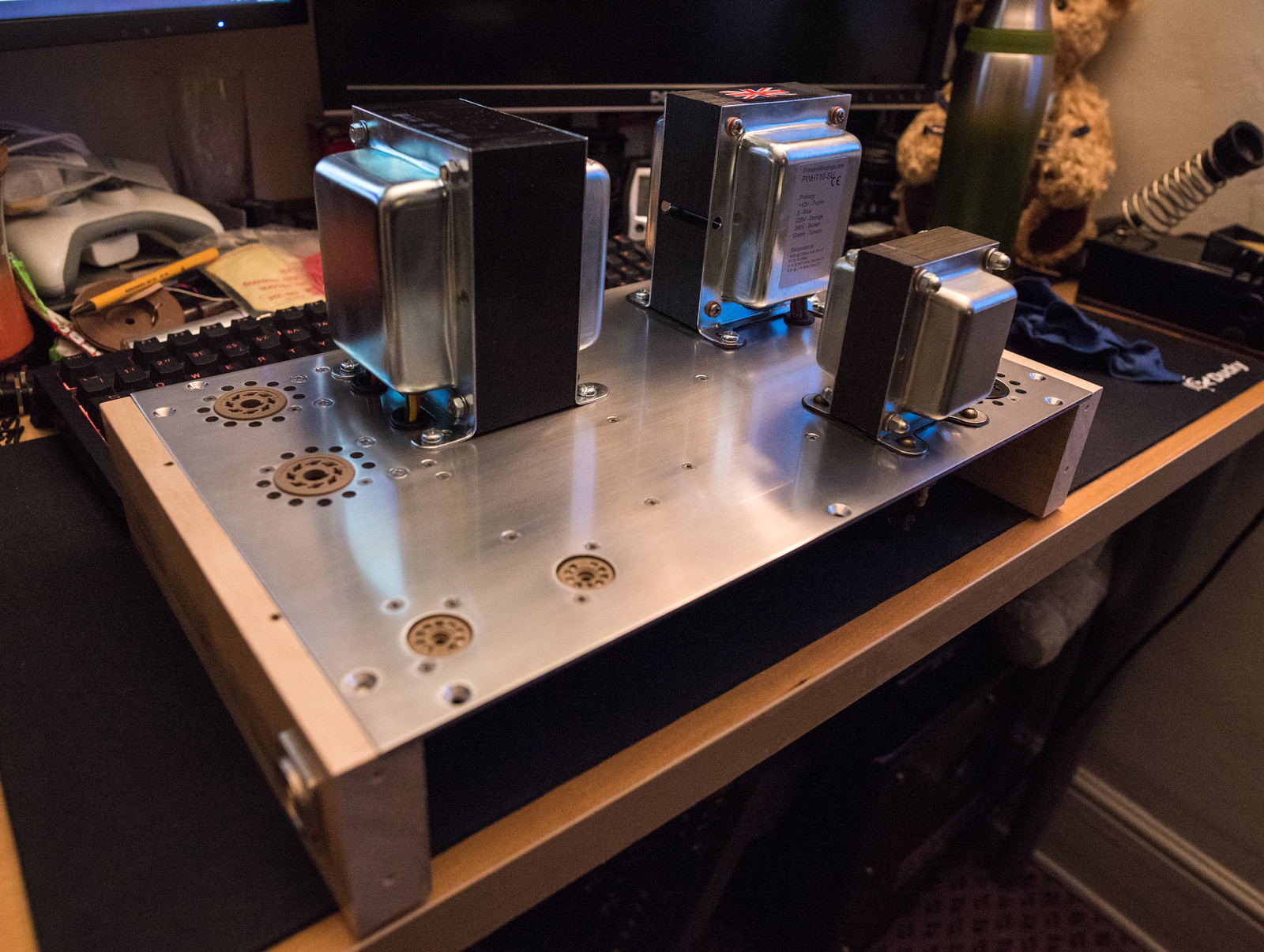
I've not abandoned work on this. Currently I am mid way through building the second unit as a more compact prototype. The main reason the first metal chassis was so large was down to me not wanting to cut up a perfectly rectangular piece of aluminium.

This version has the cathode bias components separated and located underneath the OPT allowing for a shorter chassis and shorter wiring.


I'm nearly there on the chassis. I've been reusing bits of wood off the first and second builds to save on time and wood.
I also did some sums and realised that I've been using the amp nearly every day since the end of July for 10-12 hours per day, meaning I've probably put around 1000 hours on it already. It still sounds great. These JJ KT77's have done the majority of the work. I decided that the price of the Brimar CV4006/6059's was too good to pass up so I've now got 8 of them. I got one dodgy valve with excessive hiss like the tung-sol EF806SG which langrex replaced.
I will admit to being seriously tempted to dump the sowters in preference for a pair of monolith B-8 6K6's. Even though I am certain it would provide a big improvement in the feedback and stability, I'm not necessarily sure it would provide an appreciably audible difference.
This version has the cathode bias components separated and located underneath the OPT allowing for a shorter chassis and shorter wiring.
I'm nearly there on the chassis. I've been reusing bits of wood off the first and second builds to save on time and wood.
I also did some sums and realised that I've been using the amp nearly every day since the end of July for 10-12 hours per day, meaning I've probably put around 1000 hours on it already. It still sounds great. These JJ KT77's have done the majority of the work. I decided that the price of the Brimar CV4006/6059's was too good to pass up so I've now got 8 of them. I got one dodgy valve with excessive hiss like the tung-sol EF806SG which langrex replaced.
I will admit to being seriously tempted to dump the sowters in preference for a pair of monolith B-8 6K6's. Even though I am certain it would provide a big improvement in the feedback and stability, I'm not necessarily sure it would provide an appreciably audible difference.
"Learned 1944 and Roddam 1951 had papers on that general technique for audio amp applications." I'll have a look for those,thanks for the heads up.
Nice work, those tag boards must have took ages to get right and so neat, especially as this must be the 4th time you've rebuilt this amp.
Andy.
Nice work, those tag boards must have took ages to get right and so neat, especially as this must be the 4th time you've rebuilt this amp.
Andy.
Ironically, I have no trouble making the turret boards. I can knock a set of them out in about 3 hours all soldered and ready to go. What I have a hard time with is the chassis as I am not so good at the wood and metal work. (Several days of expletives as things go awry with the cutting, drilling and routing)"Learned 1944 and Roddam 1951 had papers on that general technique for audio amp applications." I'll have a look for those, thanks for the heads up.
Nice work, those tag boards must have took ages to get right and so neat, especially as this must be the 4th time you've rebuilt this amp.
Andy.
It's been a long time since I updated this thread.
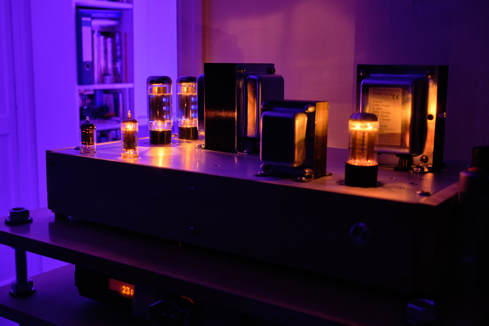
I finished the Mk IV prototype in November last year and have been using it ever since. These amps have had the proper trial by fire treatment and have been used for 10-14 hours almost daily. The first build has been doing that for around 9 months. The JJ KT77's have been working great as the main valves I've used. No problems to report with them at all. The Tung Sol and Electro-Harminox haven't seen as much use so I can't pass any judgment on their life, but they sound excellent. The EH 6CA7 do worry me slightly as G2 does look like it glows in places but I'm not sure if I'm seeing a reflection of the cathode on the grid wire as it's quite shiny. I'm also thoroughly sold on 6BR7/6059. At £8 each, they easily sound as good as a quality EF86 and they don't seem to suffer from microphonics or other noise.
When tested on the bench, the performance was very similar to the other amp which is nice as it's consistent.
1KHz square

5KHz square

10KHz square

I ended up replacing the F&T 47uF capacitors as their 500V rating would be exceeded if the valves didn't conduct. I chose the Mundorf tube caps simply because they were the right sort of dimensions to make them easy to fit. (short and fat)

It's a fairly good looking amp, which would be even better with a superior chassis and some fancy wood panelling.


I finished the Mk IV prototype in November last year and have been using it ever since. These amps have had the proper trial by fire treatment and have been used for 10-14 hours almost daily. The first build has been doing that for around 9 months. The JJ KT77's have been working great as the main valves I've used. No problems to report with them at all. The Tung Sol and Electro-Harminox haven't seen as much use so I can't pass any judgment on their life, but they sound excellent. The EH 6CA7 do worry me slightly as G2 does look like it glows in places but I'm not sure if I'm seeing a reflection of the cathode on the grid wire as it's quite shiny. I'm also thoroughly sold on 6BR7/6059. At £8 each, they easily sound as good as a quality EF86 and they don't seem to suffer from microphonics or other noise.
When tested on the bench, the performance was very similar to the other amp which is nice as it's consistent.
1KHz square
5KHz square
10KHz square
I ended up replacing the F&T 47uF capacitors as their 500V rating would be exceeded if the valves didn't conduct. I chose the Mundorf tube caps simply because they were the right sort of dimensions to make them easy to fit. (short and fat)
It's a fairly good looking amp, which would be even better with a superior chassis and some fancy wood panelling.
Pleased that you are enjoying it. Just slightly concerned your wall is also glowing blue.
Last edited:
Lol, I hadn't noticed that. It's some multicoloured lights in the room outside the door that give off the blue glow.Pleased that you are enjoying it. Just slightly concerned your wall is also glowing blue.
It's very obvious at night when the door is open.
Kei,
Very nice looking amplifier!
And now it is done, so you can enjoy listening.
It looks like the rise-time and fall-time on the 10kHz square wave scope picture, are both about
15usec.
0.35 / 15usec ~ 23kHz bandwidth.
Lots better than my hearing!
Very nice looking amplifier!
And now it is done, so you can enjoy listening.
It looks like the rise-time and fall-time on the 10kHz square wave scope picture, are both about
15usec.
0.35 / 15usec ~ 23kHz bandwidth.
Lots better than my hearing!
You've come a long way, well done for getting to the end, hat's off to you. Bet you've learned a lot though, all that knowledge and experience is priceless, non of which you would have gained if the amp worked first time.
Andy.
Andy.
I am happy to find the thread about Mullard 5-20 amplifier at your web site.
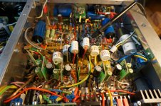
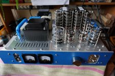
I also build the amp based on the 5-20 project however I have changed the original schematic found in Mullard ‘Tube circuits for Audio amplifiers’ brochure. Changes concern PSU unit now fully based on semiconductors, control unit now based on AtMega uPorcessor, adding phone tube circuit etc.
I also substituted EF86 input stage by ECC83 stage, ECC83 tube by 6H8C(Russian equivalent of 6SN7). Output stage with no changes EL34 (TungSol). Hammond 1650HA Output transformers were used in the project.
It took me a long time to finish mechanical part of the project as I change details of it many times which is normal in DIY projects. Now it looks little bit quirk as it is, but I don’t want to change it. No more file work.
Electrical part anticipated to be only a pleasure but the reality turned out to be more malicious. I changed schematic few times and finally I arrived at the one as enclosed.
The amp gives about 28-29W/4Ohm of power without optical distortions on the scope. uP controller gives required time sentences for tubes, controls illumination of diodes, relays work, remote communication etc.
BUT - I notices strange oscillations of 1-2Hz in the circuits. They are easily observed at the mA meters at both channels. The amplitude of them is bigger when the input acoustic signal is smaller. The amplitude of the measured cathode current is opposite from Left channel to the Right one.
I will highly appreciate any hints how to straighten the problem!
Jarek
This is caused by the negative feedback starting to become positive at very low frequencies, due to too many coupling caps and the OPT. Could you send the schematic of your design please so we can take a look as there are so many variants. You can often see the cones of the speakers moving.
There should be a return path for R31 to somewhere. Anyway the two components to change would be C33/C34 and C14. Try making each bigger then smaller and record the results. To find out the solution for me would be to put it on LTspice - but I would need the primary inductance of the OPT. The theory is to have one dominate pole in the system - usually the OPT and make all other break frequencies of the coupling much lower. This way the FB gets to unity gain without the additional phase shift reaching 180degs.
Nice work jaresky13. The original thread starter had issues with stability. Most amp builds need a little tweaking.
baudouin0's solution is the correct one, there is another tweak you could try and that's to pop a shelving network just after V1,but then and again your schematic differs quite a bit from the classic three stage type valve amp, EG voltage gain, phase splitter, OP stage. See - 100W-monobloc2-2004 7th paragraph. To clarify the shelving filter is [FONT=Helvetica, Arial, sans-serif]C4, C6, R11 and R12.[/FONT]
[FONT=Helvetica, Arial, sans-serif]
[/FONT]
[FONT=Helvetica, Arial, sans-serif]BTW, why did you decide to use that particular topology?
[/FONT]
[FONT=Helvetica, Arial, sans-serif]
[/FONT]
[FONT=Helvetica, Arial, sans-serif]Andy.
[/FONT]
By break frequencies do you mean the 3dB "cut off" frequency?usually the OPT and make all other break frequencies of the coupling much lower
baudouin0's solution is the correct one, there is another tweak you could try and that's to pop a shelving network just after V1,but then and again your schematic differs quite a bit from the classic three stage type valve amp, EG voltage gain, phase splitter, OP stage. See - 100W-monobloc2-2004 7th paragraph. To clarify the shelving filter is [FONT=Helvetica, Arial, sans-serif]C4, C6, R11 and R12.[/FONT]
[FONT=Helvetica, Arial, sans-serif]
[/FONT]
[FONT=Helvetica, Arial, sans-serif]BTW, why did you decide to use that particular topology?
[/FONT]
[FONT=Helvetica, Arial, sans-serif]
[/FONT]
[FONT=Helvetica, Arial, sans-serif]Andy.
[/FONT]
As DA says try C14=470uF first, I will simulate if you cannot get a solution. When the switch is in the HP position then there is no NFB around the amp - clever, as you don't want to take the headphone tap within the NFB forward loop where the distortion will be high. You will get quite a thump when you flip the switch mind.
What DA calls a shelving filter I call pole-zero cancellation - where you cancel one of the poles with a zero and replace with a pole much lower in frequency I used this many times. It can be placed as part of the NFB components from the speaker to the first stage. See how you go first.
Interesting topology.
Last edited:
There is a problem with making the OPT's primary inductance the dominant pole; it varies with signal level, in the wrong direction, and this is probably not considered in typical modeling programs.
A safer plan is to set the dominant pole at the grids of the output valves. This has the added advantage of minimizing clipping recovery time. C33, C34 values of u047F should stabilize with any decent OPT. Extra-large values here are a detriment to stability and a liability for clipping overload.
All good fortune,
Chris
I'd have said reduce C14, as is it's 3dB roll off is 2.3hz, this is very low, you could try a 22u to lift the LF response. Your 3dB roll off for the OP stage is also low at 0.72hz, you could try a 220n or even 22n here.
That said what would be instructive is to remove the NFB and do some frequency sweeps with no load and a capacitive load, but don't do this at high power, again the late Patrick Turner's site has some invaluable info, see - amplifier-frequency-tests . This gives you an idea of what your amps up to before applying NFB, the idea being is to sort out and potential stability issues beforehand.
Andy.
Thanks Baudouin for your suggestion with R31. Will add shelving resistorThere should be a return path for R31 to somewhere. Anyway the two components to change would be C33/C34 and C14. Try making each bigger then smaller and record the results. To find out the solution for me would be to put it on LTspice - but I would need the primary inductance of the OPT. .
I will also play with the capacity of signal caps in the output stage to get some idea about their filtering activity.
I sent the email to Hammond engineers to sent me the information about prim inductance of 1650HA transformers.
Unfortunately this weekend I'm leaving for my holidays so there will be some delay with practical activities. I hope the politicians won't distroy my plans announcing next wave of pandemium.
Jarek
baudouin0's solution is the correct one, there is another tweak you could try and that's to pop a shelving network just after V1,but then and again your schematic differs quite a bit from the classic three stage type valve amp, EG voltage gain, phase splitter, OP stage. See - 100W-monobloc2-2004 7th paragraph. To clarify the shelving filter is [FONT=Helvetica, Arial, sans-serif]C4, C6, R11 and R12.[/FONT]
[FONT=Helvetica, Arial, sans-serif]BTW, why did you decide to use that particular topology?
[/FONT]
[FONT=Helvetica, Arial, sans-serif]Andy.
[/FONT]
Good question Andy!
I started with Morgan Jones Crystal Palace. There were problems with the bread desk model probably because of Russian tubes 6H8C so I decided to change the output stage into Mulard one.
Keep staying with differential stage with CCS conected to -Eb.
Then I decided to change phase inverter into simular to Mullard's engineers.
The idea of EF86 in the first stage was repulsive for me. So I haven't tested it.
Still I am opened to new solution . May be E86C in first stage is a good idea?
I stayed with the circuits which turned out to work good. Probably the connection of such circuts together was a bad idea.
I will test shelving filters that you pointed out in Turner's solution.
Thanks, Jarek
- Home
- Amplifiers
- Tubes / Valves
- Testing newly built mullard 5-20