* Model of 1650R transformer
.SUBCKT 1650R 100 102 104 106 108 204 202 200 302 300 ; Blu Blu/Yel Red Brn/Yel Brn Yel Grn/Yel Blk/Yel Grn Blk Case
.PARAM Lp=800 ; TOTAL PRIMARY L (FROM SPECS).
.PARAM Rp=100 ; TOTAL PRIMARY R (FROM SPECS).
.PARAM Rs=.3 ; SECONDARY R (FROM SPECS).
.PARAM MM=.999947
.PARAM Lrat={4/4300} ; INDUCTANCE RATIO: (4 OHMS)/(PRIMARY).
.PARAM Cp=300p
L10 100 101 {Lp*.09}
R10 101 102 {Rp*.3}
L11 102 103 {Lp*.04}
R11 103 104 {Rp*.2}
L12 104 105 {Lp*.04}
R12 105 106 {Rp*.2}
L13 106 107 {Lp*.09}
R13 107 108 {Rp*.3}
C10 100 108 {Cp}
L20 200 201 {Lp*Lrat}
R20 201 202 {Rs}
L21 202 203 {Lp*Lrat*.1716}
R21 203 204 {Rs*.4142}
L30 300 301 {Lp*Lrat}
R30 301 302 {Rs}
K1 L10 L11 L12 L13 L20 L21 L30 {MM}
.ENDS
* Model of 1650T transformer
.SUBCKT 1650T 100 102 104 106 108 204 202 200 302 300 ; Blu Blu/Yel Red Brn/Yel Brn Yel Grn/Yel Blk/Yel Grn Blk Case
+ PARAMS: Lp=.625H Rp=2R Cp=200p Ls=10.7mH Rs=0.025R MM=.999947
L10 100 101 {36*Lp}
R10 101 102 {6*Rp}
L11 102 103 {16*Lp}
R11 103 104 {4*Rp}
L12 104 105 {16*Lp}
R12 105 106 {4*Rp}
L13 106 107 {36*Lp}
R13 107 108 {6*Rp}
C10 100 108 {Cp}
*
L20 200 201 {49*Ls}
R20 201 202 {7*Rs}
L21 202 203 {9*Ls}
R21 203 204 {3*Rs}
*
L30 300 301 {49*Ls}
R30 301 302 {7*Rs}
*
K1 L10 L11 L12 L13 L20 L21 L30 {MM}
.ENDS
The T is measured from a real transformer by matching the frequency and phase response of the simulation against a measurement. The R is best guess.
I've now been using this for just over a month and had no great problems with it at all. I added a pair of NOS mullard EF6's and GE JAN 6FQ7's which seem to work very well and confirm that the Tung-Sol EF806 I have clearly isn't operating in spec. Little I can do about it now though as I've had it since at April.
The main thing I've noticed is that it clearly it still has too much gain. It needs to drop by around 12-16dB or so. I have issues with my Marantz AV7701 pre-amp which has ground loop issues introduced by the various HDMI devices connected to it. (TV and humax pvr primarily) As a result, it has a certain amount of mains hum. A ground loop isolator between the power amp and pre amp doesn't solve it. The power amps I use have gain attenuators. Turning these down reduces the level of the mains hum.
Looking at adding an L pad on the input, I'm not sure how C1/R1/R2 on the existing input will affect things. Most designs seem to take a 500k or 1M log pot to ground and the wiper to the grid resistor. I don't really need adjustable attenuation.
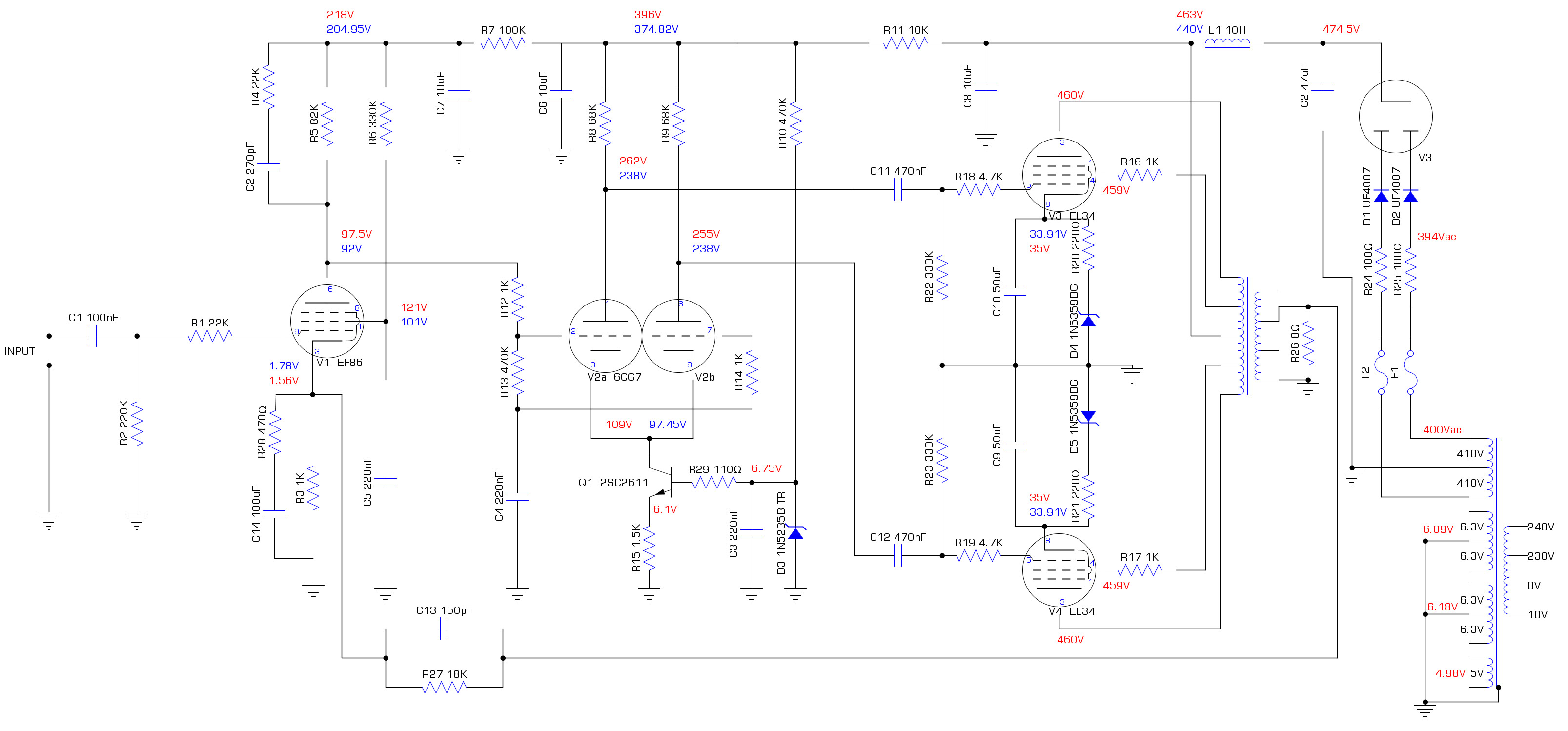
This is the current schematic.
The main thing I've noticed is that it clearly it still has too much gain. It needs to drop by around 12-16dB or so. I have issues with my Marantz AV7701 pre-amp which has ground loop issues introduced by the various HDMI devices connected to it. (TV and humax pvr primarily) As a result, it has a certain amount of mains hum. A ground loop isolator between the power amp and pre amp doesn't solve it. The power amps I use have gain attenuators. Turning these down reduces the level of the mains hum.
Looking at adding an L pad on the input, I'm not sure how C1/R1/R2 on the existing input will affect things. Most designs seem to take a 500k or 1M log pot to ground and the wiper to the grid resistor. I don't really need adjustable attenuation.
This is the current schematic.
Try ground loop isolators between tv-set and preamp
Often cabletv has a ground that is something else then you ground.
Often cabletv has a ground that is something else then you ground.
Last edited:
Sadly I can't. The problem being HDMI to/from the preamp and no one makes an isolator that is sanely priced. A muxlab fibre converter is the only one I could find but it's over £700. The joys of an AV system.
Attenuating the signal from the preamp seems to work well enough. -10dB on my solid state amp (interM R300+) reduces the hum to an inaudible level. The valve amp has more gain than the interM does set at 0dB. (not sure by how much yet)
The volume control on the preamp does not affect the level of the hum which means I get more range on the volume control. I rarely exceed -20dB on the preamp volume control and it goes up to +18dB
If you mean inline with the antenna coax, I've tried disconnecting that altogether and it doesn't seem to make a difference. Simply connecting just the HDMI with power and nothing else is all that is needed to trigger it. My old panasonic plasma appears to be an earthed device rather than double insulated like almost everything else which I suspect is the cause.
Ok. You have already tried to disconnect the coax.If you mean inline with the antenna coax, I've tried disconnecting that altogether and it doesn't seem to make a difference. Simply connecting just the HDMI with power and nothing else is all that is needed to trigger it. My old panasonic plasma appears to be an earthed device rather than double insulated like almost everything else which I suspect is the cause.
You have some work with groundings then.
This is the current schematic.
I can't open that. Am I the only one?
That was advised by Eli to reduce the chances of arc over in modern GZ34/5AR4 valve rectifiers.I wonder why do you have UF4007 fast rectifiers in there aditionally to the tube rectifier
A small detail; the decoupling cap for the screen in the input tube shouldOops, looks like I copied the thumbnail address. This should be the correct link.
connect to the cathode
So I think you have two options. The first is to isolate the amp ground from the chassis and mains earth ground. This involves using a isolated input RCA connector and speaker connectors. The amp ground is then joined to the chassis via a 10R 2W resistor. This stops the current flowing down the braid of the input coax. Always make sure the rectifier currents on C2 are returned directly to the transformer and not through any ground signal path.
The second option is to make the input pseudo differential. This would mean lifting grounds of C14/R3 and connecting them through a 10R to amp ground. You would then connect the braid of the coax to the junction of all three. Again the input RCA need to be isolated. The idea is that the hum would appear on both the grid and the cathode of the EL86 cancelling out. C1 needs to be bigger or make R2 1M to get good cancellation.
Yes having to use modern SS rectifiers does made me wonder the value of having a valve rectifier - it just makes the HT more droopy.
Last edited:
Merlin's valve wizard site also agrees with you. I just built it following the schematic but I'm happy to tweak it. Doubt it'll make any difference but I know it's considered bad practice.A small detail; the decoupling cap for the screen in the input tube should
connect to the cathode
bit of a mix up here, the preamp has the ground loop with some other devices. The valve amp to preamp has no issue. I simply wish to attenuate it's input by around 12-16dB as it's simply too sensitive. to put it another way, I've maxed out the gain on the power amp for the rear speakers and the levels are way higher out the valve amp.So I think you have two options. The first is to isolate the amp ground from the chassis and mains earth ground. This involves using a isolated input RCA connector and speaker connectors. The amp ground is then joined to the chassis via a 10R 2W resistor. This stops the current flowing down the braid of the input coax. Always make sure the rectifier currents on C2 are returned directly to the transformer and not through any ground signal path.
The second option is to make the input pseudo differential. This would mean lifting grounds of C14/R3 and connecting them through a 10R to amp ground. You would then connect the braid of the coax to the junction of all three. Again the input RCA need to be isolated. The idea is that the hum would appear on both the grid and the cathode of the EF86 cancelling out. C1 needs to be bigger or make R2 1M to get good cancellation.
Yes having to use modern SS rectifiers does made me wonder the value of having a valve rectifier - it just makes the HT more droopy.
I simply wish to attenuate it's input by around 12-16dB as it's simply too sensitive. to put it another way, I've maxed out the gain on the power amp for the rear speakers and the levels are way higher out the valve amp.
That doesn't make sense. Attenuate + amplify = noise. What you want to do here is reduce the maxed-out gain. Not just compensate for it.
EJP
- Home
- Amplifiers
- Tubes / Valves
- Testing newly built mullard 5-20