Hey I got another idea about the bias. First of all cathode bias is called auto bias for a reason. No need for bias adjustment. Now with a resistor in there after the zener its still doing the same prupose it has some give to it butmore "stiff".
Could we use a current source in the cathodes of the EL34 set for whatever we want (lets say 50mA) and put a bypass capacitor of large value (470uF) across the current source of the valve? This would more accurate set the DC bias point of the tubes and kinda overcomplicate things aswell. The bypass capacitor would basically serve the purpose same as in the original circuit. Above all that the 470uF capacitor should prevent the bias point moving out of spec. I know I am trying to do something absurd after all the proper way to bias tubes is by grid. but just a thought. Maybe if you could test this baouduin0
This is just a idea not necessary to implement but just been thinking of it.
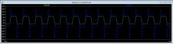
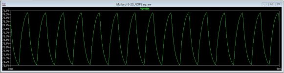
I found a 5-20 LTspice simulation on this site (somewhere) and ran a couple of tests with a modest power output. The tests are using a roughly 15KHz squarish wave.
IMO, a 15 KHz. square wave is an unfair and, perhaps, meaningless test condition. 😡 "Tons" of RF is present in that signal. JMO, you tweak the amp, on the bench, to get the best looking (for tilt/ringing/overshoot) O/P on an o'scope, using a 2 KHZ. square wave as the driving signal. Don't ask the O/P "iron" to perform a task clearly beyond its capability.
A 15 KHz. square wave signal could/would overtax the phenomenally good "iron" found in Harman-Kardon Citation II specimens.

Hey I got another idea about the bias. First of all cathode bias is called auto bias for a reason. No need for bias adjustment. Now with a resistor in there after the zener its still doing the same prupose it has some give to it butmore "stiff".
Could we use a current source in the cathodes of the EL34 set for whatever we want (lets say 50mA) and put a bypass capacitor of large value (470uF) across the current source of the valve? This would more accurate set the DC bias point of the tubes and kinda overcomplicate things aswell. The bypass capacitor would basically serve the purpose same as in the original circuit. Above all that the 470uF capacitor should prevent the bias point moving out of spec. I know I am trying to do something absurd after all the proper way to bias tubes is by grid. but just a thought. Maybe if you could test this baouduin0
This is just a idea not necessary to implement but just been thinking of it.
The problem is that with a current source when you wind up the output level into class B, the average current will need to increase. If you keep passing 50ma then then voltage across the 470uF would go up and eventually the EL34 would be biased into crossover distortion when the average will get back to 50ma. So its actually the wrong thing to do.
However if you could adjust the CCS based on signal level that would be interesting. Maybe even a CCS with a zener in parrallel so that the zener only conducts with large signals.
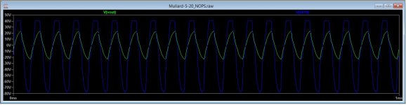
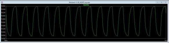
Some more results below. These are unrealistic operating conditions of a continuous 15-20KHz 20W waveform which would instantly blow up the tweeter in any speaker. Below are EL34 grid and output waveforms for 15KHz sq wave and 20KHz sinewave and they have caused the DC operating conditions to get messed up. I don't think a CCS will change anything and the relatively small improvement of changing the LTP valve and load is likely to be outweighed by the loss of gain and increased non-linearity.
Attachments
Last edited:
My criteria for a good amp is can it pass a full 15KHz sinewave without visible distortion. It is an unrealistic test, but it does demonstrate you have adequate slew rate handling. Interesting that you results are wore than mine maybe your transformer is more accurate.
I think that due to my solid state back ground, my expectations of how a valve amp would behave have been a bit skewed. It's reassuring to see that they all get a bit out of shape in the 10KHz+ region at higher power levels as I hadn't expected this. I just expected the amp to clip and that was that. My preference was to initally build this as a mullard then play with it to see where I could improve it. At this point it's just become a case of make it as good as it can be then leave it.
Anyway, one question I do have regarding the 6CG7 conversion, what is the input sensitivity like for full power output? My preference is for 500mV to 1V for full power out. Lastly, was the BZX85B6V8-TR or 1N5235BTR a suitable zener for the 6.8V position in the CCS?
Anyway, one question I do have regarding the 6CG7 conversion, what is the input sensitivity like for full power output? My preference is for 500mV to 1V for full power out. Lastly, was the BZX85B6V8-TR or 1N5235BTR a suitable zener for the 6.8V position in the CCS?
I think that due to my solid state back ground, my expectations of how a valve amp would behave have been a bit skewed. It's reassuring to see that they all get a bit out of shape in the 10KHz+ region at higher power levels as I hadn't expected this. I just expected the amp to clip and that was that. My preference was to initally build this as a mullard then play with it to see where I could improve it. At this point it's just become a case of make it as good as it can be then leave it.
Anyway, one question I do have regarding the 6CG7 conversion, what is the input sensitivity like for full power output? My preference is for 500mV to 1V for full power out. Lastly, was the BZX85B6V8-TR or 1N5235BTR a suitable zener for the 6.8V position in the CCS?
No I completely understand - I too come from a solid state background, it does make for an interesting discussion - and you will be able to improve on the design you have. AS for the zener its not critical I would get a 500mW device say bzy88c6v8. What OPT are you using it may have been mentioned.
Last edited:
Sounds good, RS don’t have a bzy88 but the bzx85 is 1-1.3W which is obviously ample and the 1N5235BTR is 500mW which is perfect.No I completely understand - I too come from a solid state background, it does make for an interesting discussion - and you will be able to improve on the design you have. AS for the zener its not critical I would get a 500mW device say bzy88c6v8. What OPT are you using it may have been mentioned.
These output transformers are Sowter UA-21.
Last edited:
I have now set some 'initial conditions' to skip the 3 second settling period which made LTSpice VERY slow. Firstly, I have no idea if the output transformer model is likely to have any resemblance to yours but the simulator results have shown similar characteristics to your experience. There are 2 traces for 20KHz below, the first is just before the driver pushes the EL34 into grid current at around 25W (20V peak) and the 2nd is after it enters grid current. This is not a limit of the driver it is the output stage. The driver waveforms look very distorted as the -ve feedback is making corrections to maintain the input waveform shape on the output.
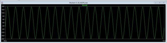
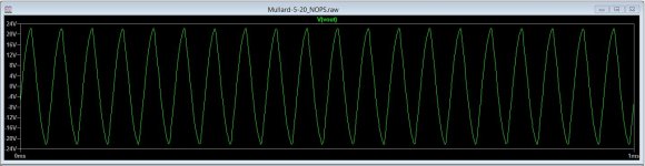
Based on LTSpice, the 5-20 driver is not showing any significant limitations and the 30dB -ve feedback appears quite capable of keeping the output on track.
Based on LTSpice, the 5-20 driver is not showing any significant limitations and the 30dB -ve feedback appears quite capable of keeping the output on track.
Attachments
Last edited:
Regarding post # 203:
Most square wave generators have a constant rise time.
In that case, the upper bandwidth of the square wave is a constant.
A square wave generator with a Gaussian response will have upper bandwidth as follows:
Bandwidth = 0.35/(Rise Time). Where Rise Time is from 10% to 90%. That is the -3dB bandwidth.
A 2 kHz square wave that has a 4us Rise Time has upper bandwidth of 87.5 kHz.
A15 kHz square wave that has a 4us Rise Time has upper bandwidth of 87.5 kHz.
There is no difference of the top frequencies when the generator is set to either
2 kHz or 15 kHz.
A really good square wave generator with a 0.1us Rise time has upper frequency bandwidth of 3.5 MHz.
2 kHz and 15 kHz square waves off of that generator both have 3.5 MHz harmonics.
When you adjust the scope to show two complete cycles of 2 kHz square wave, those upper harmonics are still there, even if you do not see them. If there is ringing at 500 KHz, you do not have enough resolution at that scope setting to see that.
Square wave testing on a scope requires knowing what to look for, both with a low frequency square wave, and with a high frequency square wave. A 100 Hz square wave will show the low frequency response, the flatter the top, the better the low frequency response.
A 5 kHz or 10kHz square wave will show the high frequency response.
The kHz frequencies of the 5 kHz square wave are 5, 15, 25, 35, . . . and so on, all odd harmonics, all the way to the -3dB bandwidth (and beyond).
The kHz frequencies of the 10 kHz square wave are 10, 20, 30, 40, . . . and so on, all odd harmonics, all the way to the -3dB bandwidth (and beyond).
A square wave generator that has a very bad Rise Time can not be used to test your amplifier's upper frequency response, nor to test for ringing, overshoot, dribble up, etc.
You should measure the Rise Time of the square wave generator first. Then calculate its bandwidth = 0.35/(Rise Time).
Then measure the rise time of your amplifier.
If the rise time of the square wave generator is the same as the true rise time of the amplifier, you do not get 2X the rise time of either;
instead you get 1.4X the rise time of either.
Example: The generator measures 5us Rise Time. Connect the generator into the amplifier, and suppose the amplifier output gives a combination Rise Time of 7us.
Therefore, the amplifier rise time is also 5 us.
Last edited:
The spec sheet for the TG2000 function generator I’m using says <22ns (0.022us) rise time. That says it can quite easily pump lots of RF harmonics in with ease. I would use my Lindos set but currently the generator isn’t working properly and the analyser has a dead lcd.
Fast rise time will get lost at the EF86 as the anode is slugged by the V2 miller capacitance. Below are waveforms for EF86 anode, open loop with a 15KHz square wave input (5uS rise time), with and without V2 connected. This appears to be the weak link in the 5-20 design rather than the LTP.
It would be interesting to see what the waveform looks like on your triode wired EF86 with a square wave but you would need to remove the RC network on the anode and disconnect feedback. My gut feeling though is that any changes to make it 'faster' will only result in instability.
It would be interesting to see what the waveform looks like on your triode wired EF86 with a square wave but you would need to remove the RC network on the anode and disconnect feedback. My gut feeling though is that any changes to make it 'faster' will only result in instability.
Attachments
Last edited:
Kei,
Go ahead and use a generator that has a very fast rise time. It does not hurt anything.
The harmonics fall off very rapidly.
Most amplifiers have limited bandwidth. Single ended, push pull, with negative feedback, without negative feedback, etc.
Square Wave fundamental and harmonic amplitudes:
Fundamental 0 dB (reference)
3rd harmonic -9.5 dB
5th harmonic -14 dB
7th harmonic -16.9 dB
9th harmonic -19 dB
11th harmonic -20.8 dB
13th harmonic -22.3 dB
15th harmonic -23.5 dB
- - -
51st harmonic -34.2 dB
- - - and so on
But do be sure to terminate a generator that has a 50 Ohm output.
Use a 50 Ohm coax from the generator.
Use a 50 Ohm terminator at the far end of the 50 Ohm coax (the input to the amplifier).
Either use a 50 Ohm Through terminator, or use a BNC-T, and a 50 Ohm terminator on one port.
Use an adapter to connect to the amplifier input (like a BNC to RCA Phono, for example).
I have now set some 'initial conditions' to skip the 3 second settling period which made LTSpice VERY slow. Firstly, I have no idea if the output transformer model is likely to have any resemblance to yours but the simulator results have shown similar characteristics to your experience. There are 2 traces for 20KHz below, the first is just before the driver pushes the EL34 into grid current at around 25W (20V peak) and the 2nd is after it enters grid current. This is not a limit of the driver it is the output stage. The driver waveforms look very distorted as the -ve feedback is making corrections to maintain the input waveform shape on the output.
Based on LTSpice, the 5-20 driver is not showing any significant limitations and the 30dB -ve feedback appears quite capable of keeping the output on track.
Yep I had to add a very high value resistor from the V2 cathodes to ground when using a CCS. There are also options on LT spice for the DC algorithms. The transformer is very similar - I notice the data sheet has all the inductance and coupling factor. The only thing missing is the primary capacitance which you can place as a lumped element across the plates - typically 1-2nF. The data sheet also has a frequency response. Its worth just checking the transformer on its own in LT spice in the same test circuit to see if yours is similar although you really need a phase response. Without the phase data you may struggle to get the correct components for the GNF. Spmebody may have measured one up on the bench - that's what I had to do with the 1650T OPT.
Last edited:
Hopefully the bits and pieces I need to try out the 6CG7 PI should be arriving tomorrow. Something that crossed my mind having come across it in reading, how does running EF86 as a pentode affect the frequency response what with impedance and miller effect?
Also based on the simulations of the EF86->6CG7>EL34, what should the input sensitivity be. i.e how many mV in for x watts out?
Also based on the simulations of the EF86->6CG7>EL34, what should the input sensitivity be. i.e how many mV in for x watts out?
Could you post your proposed schematic with the 6cg7 just so we can check we have the bits correct.
I was using your schematic from post 186. I may well leave the output stage cathode bias as is for now, but I have got the necessary components to add the zeners. C6 can't be 22uF as I don't have one. I have either 10uF or 47uF. I'm working on drawing up a proper schematic including the psu at the moment.Could you post your proposed schematic with the 6cg7 just so we can check we have the bits correct.
OK yep 47uF would be fine. Yes you need to move back to pentode mode in the EF86 as the gain will be too low. It more linear anyway. I don't have the exact model of the output transformer at the moment so the FB may be approximate. Interestingly its very very close to the dynaco modified mullard circuit which pjl123 simulated. You could go with this tried and tested just would replace the 22k with the CCS. This has a 12pF back from the screen of the primary of the transformer to help with the NFB. Again the NFB will need some tweeks for your transformer.
I understand you don't want to try the output zeners yet. It will allow you to operate the EL34's at a lower quiescent current (as they are close to red plating at the moment) while giving you a bit more output power and much less distortion near full output.
I understand you don't want to try the output zeners yet. It will allow you to operate the EL34's at a lower quiescent current (as they are close to red plating at the moment) while giving you a bit more output power and much less distortion near full output.
Last edited:
- Home
- Amplifiers
- Tubes / Valves
- Testing newly built mullard 5-20