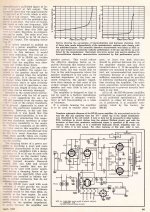
I've plotted a new graph with feedback connected using 1nF/3.3K for C5/R7 and the step network you suggested around R4 (4.7K/470pF) Performance looks pretty good. I also plotted open loop onto the same graph. There are still the couple of oddities that continue to baffle me. I put the new EF86 back in and the voltages have shifted back again, close to what we were seeing before.
EF86
Supply - 225.7V
plate - 140.8V
Cathode - 0.87V
5751
Supply - 407V
Plate 1 - 247.2V
Plate 2 - 247.2V
Cathode - 118.5V
G1-K - 1.08V
G2-K - 1.04V
There are also big differences in the behaviour between the positive half and negative half. The negative half still rings on square waves, the positive half does not. I would have expected a mirror image if things were balanced. LF is still a bit unstable particularly below 20Hz, I guess it's easier to filter the LF out at the input.
The LF is a problem as the transformer pole and the 100nF/470k pole on the EL34 grid are at similar frequencies. If 100nF was much better than 470nF you could make this pole higher in frequency try 47nF (8Hz) or even 22nF (16Hz). A lot of amps do this to overcome the LF stability. They are in the NF loop so won't make much difference to the overall response. They should sort out your LF.
I would suggest an input blocking cap anyway.
A bit more of a think is required for the negative ring. You could lower the 82K on the 12AX7 to 68K just to make sure with the correct voltage on V1 you have say 280v on V2. I did try 1nF and 10K on the plate of V4. Not sure will take a look in the morning.
Last edited:
I would suggest an input blocking cap anyway.
I regard filtering infrasonic noise out at the I/P of any tube amp that contains a GNFB loop as a matter of routine. Protect the O/P transformer against core saturation. Setting the pole's F3 in the 16-18 Hz. range usually works well. If the intended speakers lack stellar bass extension, placing that pole's F3 somewhere under 30 Hz. can work out nicely. Please keep in mind that the lowest tone a "standard" double bass produces is 41 Hz. Only 32 foot organ stops and big drums produce sound in the 1st octave.
The NFB will compensate for the roll off as C9/C10 are in the feedback loop and making then 47nF or 22nF should improve the LF stability. I have no idea on your asymmetric response except the simulation does exactly the same thing! Maybe somebody else can see why it only appears on closing the FB.
Last edited:
DC voltages at ECC83...ECC83 across pin 7 & 8 = 0.62V
ECC83 across pin 2 & 3 = 0.44V these readings are now too far the other way, indicating the valve is biased too hot, the valves Vgk's should be at least 2v, as it is on the positive going part of a sine IP, your LTP will start to run into grid current, then the triode turns into a diode and the negative part of the sine out will be clipped, cut off, which is what looks like happening a few posts back. What is weird is how can one set of readings indicate the valve is in cutoff - IE Vgk 14v, then another set of readings indicate it's biased too hot???
As it is this amp appears to have two main problems 1) Odd DC conditions, & incorrectly biased ECC83 LTP and 2) stability issues. Until 1) is sorted it's no use trying to deal with 2). If this amp was on my bench I'd be looking at starting from scratch, not necessarily ripping everything out, but going right back to step one and getting all the DC conditions bang on, then when that's right pop a signal in and follow it through each stage without NFB applied making sure the sine is good going into the OP stage. I think things are further confused by trying to tack on the CB implementation of the circuit and changing components at random.
Very frustrating sitting here miles away and not being able to help in person.
Andy.
What’s strange is I’ve seen vgk on ecc83 of 2.2 yesterday when I had swapped out the newer Tung sol EF86 for the vintage GE 6267 and the new Tung sol 12AX7 for the old GE 5751. See the attached drawing with voltages listed in this post. I swapped out just the EF86 back to the new Tung sol later that day without making any other changes and vgk on ECC83 dropped to 1.08V/1.04V. I’m at a loss as to why the DC conditions are defying logic. The component values are correct and have been double checked against their marked values. baudouin0‘s simulation of the build using the same value components results in textbook dc conditions. I’d double checked my soldering but I think I’ll triple check it today as something is definitely not right with V1/V2 on this.DC voltages at ECC83...ECC83 across pin 7 & 8 = 0.62V
ECC83 across pin 2 & 3 = 0.44V these readings are now too far the other way, indicating the valve is biased too hot, the valves Vgk's should be at least 2v, as it is on the positive going part of a sine IP, your LTP will start to run into grid current, then the triode turns into a diode and the negative part of the sine out will be clipped, cut off, which is what looks like happening a few posts back. What is weird is how can one set of readings indicate the valve is in cutoff - IE Vgk 14v, then another set of readings indicate it's biased too hot???
As it is this amp appears to have two main problems 1) Odd DC conditions, & incorrectly biased ECC83 LTP and 2) stability issues. Until 1) is sorted it's no use trying to deal with 2). If this amp was on my bench I'd be looking at starting from scratch, not necessarily ripping everything out, but going right back to step one and getting all the DC conditions bang on, then when that's right pop a signal in and follow it through each stage without NFB applied making sure the sine is good going into the OP stage. I think things are further confused by trying to tack on the CB implementation of the circuit and changing components at random.
Very frustrating sitting here miles away and not being able to help in person.
Andy.
If nothing else, I still have the mk1 in virtually complete condition. I only robbed it of the dropping resistors and the main filter cap. Other than a lot of oscillating, that worked and followed the expected dc conditions. It also had zero mains hum which the mk2 does have. It’s a ground loop as it doesn’t do it with the input disconnected.
The metal chassis build is currently sat waiting for the hole punch set to arrive. I have everything else I need.
Last edited:
I would go with the EF86 and the 5751 for now. The ECC83 bias is controlled by the current in the 82k resistor, the the vgk will just settle to what it needs to be, why your ECC83 is so low is a puzzle. Just check your soldering. The other possibility is HF oscillation - the V2 grid which is connected to ground through the cap ought to have say 1K resistor in series with the grid. Your meter lead might set it off so when you measure the plate all looks ok.
Last edited:

OK two things - first on the simulation with the 12ax7 fitted I get 23dB of NFB. This is too big and will make the amp very difficult to get stable. I suggest you move to 17dB of FB by increasing the NFB resistor to 5k6. and the anode resistor 470. I've made an number of small changes on the simulation schematic for you to browse over.
The negative ringing took some investigation. Basically the V2 grid on the right is biased from the average DC of the signal. If the drive waveform becomes asymmetric then the average DC is not the .5 * (peak positive + peak negative) of the pulse. This causes the plate voltages on V2 to be no longer centered. This changes the gain for the positive and negative peaks and effects the NFB stability.
The drive waveform becomes slightly asymmetric due the first stage. The very fast edges on the input square wave cause non-linearity in V1 (see current waveform). This translates to plate inbalance (see red and blue traces)
Increasing the EL34 screen resistors to 2k2 helps stability too.
I think we may have started with not the best schematic and are gradually pulling it apart. But its very interesting learning!
Last edited:
I think we may have started with not the best schematic and are gradually pulling it apart. But its very interesting learning!
Please remember that I stated the topology of the 5-20 is fine, but Mullard's implementation is, 1st & foremost, sales oriented. IMO, both EICO and H/K did better jobs of implementing the voltage amplifier DC coupled to differential gain block phase splitter concept.
Something I have noticed that I'd not picked up on before is that the new tung sol EF86 is actually an EF806SG which may or may not have some bearing on this. I realise 12AX7 vs 5751 is different, but I thought 12AX7 and ECC83 were identical.I would go with the EF86 and the 5751 for now. The ECC83 bias is controlled by the current in the 82k resistor, the the vgk will just settle to what it needs to be, why your ECC83 is so low is a puzzle. Just check your soldering. The other possibility is HF oscillation - the V2 grid which is connected to ground through the cap ought to have say 1K resistor in series with the grid. Your meter lead might set it off so when you measure the plate all looks ok.
I originally looked at the HF-60 as a frame of reference. It doesn't look that hard to convert the phase splitter to a 6CG7, although I imagine I'd have to make more changes than the apparent differences would suggest. I chose the mullard as I had the book and it was considered "well proven". I've probably not helped myself in some respects by performing the Claus Byrith modifications to the front end as I wanted less gain. I also have the GEC valve amplifier book and the Vanderveen book too. I'm fully prepared to modify this design to whatever works properly provided I don't have to buy lots of additional parts to do it. Small cheap parts I don't mind.Please remember that I stated the topology of the 5-20 is fine, but Mullard's implementation is, 1st & foremost, sales oriented. IMO, both EICO and H/K did better jobs of implementing the voltage amplifier DC coupled to differential gain block phase splitter concept.
Anyway, I've been over the soldering at the connections to V1 and V2. There were some okish looking joints which I've redone. I've also added a 6.8nF capacitor at the input to help filter out infrasonic.

Attachments
Yep I have the Mullard publication. Yes 30dB of feedback and .05% distortion - really.
Obviously, the distortion numbers "disease" made its appearance very early on. Adjust the amount of NFB downwards. If the setup produces 0.3% THD, at full power, that's eminently satisfactory. Very few, if any, people can hear 0.5% THD with a sine wave. Complex musical waveforms increase detection difficulty.
Logically, if there was HF oscillation, I ought to be able to see it on the scope. The lack of a shielded metal chassis on all my test builds makes me wonder. I'm still waiting on the hole punches to arrive which will allow me to remake the amp in aluminium.I would go with the EF86 and the 5751 for now. The ECC83 bias is controlled by the current in the 82k resistor, the the vgk will just settle to what it needs to be, why your ECC83 is so low is a puzzle. Just check your soldering. The other possibility is HF oscillation - the V2 grid which is connected to ground through the cap ought to have say 1K resistor in series with the grid. Your meter lead might set it off so when you measure the plate all looks ok.
Interesting that it requires so much tinkering to fix. The standard design didn't have any of that so logically it would also have suffered from the same issues.View attachment 844874
OK two things - first on the simulation with the 12ax7 fitted I get 23dB of NFB. This is too big and will make the amp very difficult to get stable. I suggest you move to 17dB of FB by increasing the NFB resistor to 5k6. and the anode resistor 470. I've made an number of small changes on the simulation schematic for you to browse over.
The negative ringing took some investigation. Basically the V2 grid on the right is biased from the average DC of the signal. If the drive waveform becomes asymmetric then the average DC is not the .5 * (peak positive + peak negative) of the pulse. This causes the plate voltages on V2 to be no longer centered. This changes the gain for the positive and negative peaks and effects the NFB stability.
The drive waveform becomes slightly asymmetric due the first stage. The very fast edges on the input square wave cause non-linearity in V1 (see current waveform). This translates to plate inbalance (see red and blue traces)
Increasing the EL34 screen resistors to 2k2 helps stability too.
I think we may have started with not the best schematic and are gradually pulling it apart. But its very interesting learning!
If the Eico is a much better front end, what stops me from being able to just integrate the HF-60 V1/V2 arrangement into my design using a 6CG7 instead of 6SN7?Please remember that I stated the topology of the 5-20 is fine, but Mullard's implementation is, 1st & foremost, sales oriented. IMO, both EICO and H/K did better jobs of implementing the voltage amplifier DC coupled to differential gain block phase splitter concept.
Maybe some spice simulations could be done using EF86 into a 6CG7 splitter. I've got no attachment to the 12AX7 or the standard mullard design. I tried to stick with the "tried and tested" design as the information was readily available with expected voltages etc plotted out.
Q. Why did you move over to triode mode on the EF86? You will see the plate in balance on a scope with a couple of 100x probes.
Your 6cg7 is more like a 12au7. These have too low a gain and the balance becomes a lot worse unless you are prepared to move to a CCS as the current tail.
Your 6cg7 is more like a 12au7. These have too low a gain and the balance becomes a lot worse unless you are prepared to move to a CCS as the current tail.
Last edited:
Less gain. The standard mullard design is just too sensitive. 0.5-1V for full output is far better for my preamp. What with the oscillation problems I was having, less gain and reduced feedback made sense.Q. Why did you move over to triode mode on the EF86?
I still have my first build using my own layout which is still standard mullard. In some respects, it was superior as there were no problems with ground loops and hum.
Less gain. The standard mullard design is just too sensitive. 0.5-1V for full output is far better for my preamp. What with the oscillation problems I was having, less gain and reduced feedback made sense.
I still have my first build using my own layout which is still standard mullard. In some respects, it was superior as there were no problems with ground loops and hum.
OK see my comments on the 6cg7.
What about doing it as per the Eico schematic where EF86 is used as a pentode? I'm just thinking that the world over thinks the EF86 / 12AX7 combo was a poor choice and what is considered "better".Your 6cg7 is more like a 12au7. These have too low a gain and the balance becomes a lot worse unless you are prepared to move to a CCS as the current tail.
No doubt a CCS would improve things there too. If a CCS can be implemented without the need for separate power supplies, I'm happy to try it if it can be done on veroboard in the space I have.
The CCS you were looking at before is fine. Its not what the world thinks but the science behind. However you will have to decide which route to take. We can only make suggestions. For my opinion yes I would use the EF86 in pentode mode, I would use something like a 12AT7 as the phase splitr, I would get more current through the 12AT7 by using lower plate resistors so that the pole are higher. I would definitely use a CCS. I would get rid of some of the self bias with zeners on the cathodes and reduce the standing current in the EL34's so they don't red plate. But that's a lot of change! However what you have now will work.
Last edited:
Will any of these NPN transistors be suitable for use as a CCS?The CCS you were looking at before is fine. Its not what the world thinks but the science behind. However you will have to decide which route to take. We can only make suggestions. For my opinion yes I would use the EF86 in pentode mode, I would use something like a 12AT7 as the phase splitr, I would get more current through the 12AT7 by using lower plate resistors so that the pole are higher. I would definitely use a CCS. I would get rid of some of the self bias with zeners on the cathodes and reduce the standing current in the EL34's so they don't red plate. But that's a lot of change! However what you have now will work.
2SC2611
2N3440
2SC2229
How would 12AT7 compare with the likes of 6CG7 or 12BH7? I already have an ECC81, so it wouldn't be difficult to try this out as an experiment.
How would 12AT7 compare with the likes of 6CG7 or 12BH7?
Net gain will be only slightly less than that realized with a 12AX7. The much lower RP compensates for the smaller μ.
Set the tail CCS for 6 mA. and adjust the value of the LTP's plate loading resistors as is necessary.
- Home
- Amplifiers
- Tubes / Valves
- Testing newly built mullard 5-20