I can answer the last question thats the negative feedback correcting the slow response of the output transformer etc. Could you re-post your latest exact schematic there have have several and I don't know which you have built to.
So that is actually normal? I admit, I don't know what is expected. Presumably, it is wiser to do V1/V2 measurements with no feedback to mess about with things.I can answer the last question thats the negative feedback correcting the slow response of the output transformer etc. Could you re-post your latest exact schematic there have have several and I don't know which you have built to.
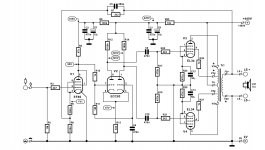
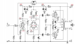
The attached schematic is what I currently have assembled.
Attachments
OK lets go back a bit. In the steady stage could you record the voltages on V2 for each pin. The reason for this is that the grid cathode voltage should be around 2v not 14v. We need to find the cause of this first. Yout are using a modern high impedance meter.
Yes, temporary removal of feedback will enable pinpointing whatSo that is actually normal? I admit, I don't know what is expected. Presumably, it is wiser to do V1/V2 measurements with no feedback to mess about with things.
The attached schematic is what I currently have assembled.
happens stage by stage.
You can even pull the EL34 for a while to examine better, note voltages
at output of phase inverter for later comparation.
So this is a simulation of V1 and V2 from your schematic. The voltages are very close to those on the schematic.

Also to note, this 12AX7 that I'm currently using is supposed to be a matched part for phase inverter use.
DC voltages measured as follows: (Fluke 28 10M impedance)
ECC83 across pins 7 & 8 = rapidly shifting between 0V and 0.6V
ECC83 across pins 2 & 3 = rapidly shifting between 0.3V and 0.6V
ECC83 pin 6 to ground = 254V fluctuating down to 240V
ECC83 pin 1 to ground = 260V
EF 86 pin 6 to ground = 136V
EF86 pin 3 to ground = 0.9V
EF86 across pins 9 & 3 = 0.78V

You should not see any fluctuating voltages. NFB should be disconnected. This is not the same as the 14v you reported earlier between 7 and 8. I am looking at the complete amp on LT spice now.
Its possible with the NFB connected you have LF instability - you did say you had changed some of the caps - could you indicate which.
One thing I would say - because its a self bias amp, if you drive it hard then the voltage on the cathodes of the EL34's will start to increase to to point you won't have enough bias and you get crossover distortion. Both your traces and the simulation show this.

OK so your amp as it stands (assuming the transformer is similar to the simulation) is neither stable at LF or HF. The LF issue has been compounded by changing the caps on the cathodes of the EL34's from 50uF to 470uF. This will make the amp very close to oscillation at 1Hz.
View attachment 844378
You should not see any fluctuating voltages. NFB should be disconnected. This is not the same as the 14v you reported earlier between 7 and 8. I am looking at the complete amp on LT spice now.
Its possible with the NFB connected you have LF instability - you did say you had changed some of the caps - could you indicate which.
One thing I would say - because its a self bias amp, if you drive it hard then the voltage on the cathodes of the EL34's will start to increase to to point you won't have enough bias and you get crossover distortion. Both your traces and the simulation show this.
NFB was still connected when I measured these voltages. I think I may have made an error with the 117V measurement at pin 6 on EF86 previously. (I forgot to write it down at the time) The measurements I made today are definitely correct as I wrote each one down.
The original elektor schematic calls for C6 to be 220nF and C9 & 10 to be 100nF. Mine has 470nF in all of those positions. The original Claus Byrith schematic had 470nF in all these which is why mine is like it. This is what the elektor text mentions regarding the change in c9/10 values.
In the original design, the screen coupling capacitors for the output valves (C9 & C10) had a value of 470nF. The current through the output valves proved to have rather large fluctuations at a very low frequency (0.2–0.5 Hz), which were also present
at the loudspeaker output. This was probably due to small variations in the negative grid voltage. Since these fluctuations have a small amplitude and the output transformer has a large self-inductance, they are not blocked by the output transformer, and they find their way to the amplifier input via the negative-feedback network. This phenomenon was reduced to an accept-able level by decreasing the value of C9 and C10 to 100 nF. This does not have any audible effect on the reproduction of low frequencies.
I'm certainly open to changing these over as I have some 0.1uF caps to do it.
The caps on the EL34 cathodes are 50uF, I've never changed that.View attachment 844387
OK so your amp as it stands (assuming the transformer is similar to the simulation) is neither stable at LF or HF. The LF issue has been compounded by changing the caps on the cathodes of the EL34's from 50uF to 470uF. This will make the amp very close to oscillation at 1Hz.
OK I went back to one of your earlier schematics and there are extra components - one for a dominate pole around the plate of V1 and a zero for the LF (across R5). I have done a very rough feedback changes for you but without a bode plot its a bug guess.

I know this can be very confusing. First do your measurements open loop. I think the fluttering you see is LF instability. Certainly this is hinted at when the C9 and C10 have undergone changes. Basically it will get more stable with .1uF there. I put the cap back across R5 to help with the LF stability. However this changes the gain of the first stage (and the FB) and that is why R7 is double the value. To get HF stability you will need a dominate pole - I added a cap and resistor across R4. Note as you are in triode mode the plate impedance is much lower so the cap there is bigger.
With NFB disconnected, I do see stable voltages. These voltages are the same as I measured previously though.
ECC83 across pin 7 & 8 = 0.62V
ECC83 across pin 2 & 3 = 0.44V
Previous experience with that step network around Ra of EF86 is that it seems to significantly increase ringing. I've tried variable components in there with no luck. It seems to behave better without it.
I've taken a load of shots of lissajous curves to try and do a bode plot but the mind boggles. These were taken at 20mV input. CH1 is output at the 8R secondary and CH2 is at the input socket before R3.
Lissajous Curves
With NFB disconnected, I do see stable voltages. These voltages are the same as I measured previously though.
ECC83 across pin 7 & 8 = 0.62V
ECC83 across pin 2 & 3 = 0.44V
Previous experience with that step network around Ra of EF86 is that it seems to significantly increase ringing. I've tried variable components in there with no luck. It seems to behave better without it.
I've taken a load of shots of lissajous curves to try and do a bode plot but the mind boggles. These were taken at 20mV input. CH1 is output at the 8R secondary and CH2 is at the input socket before R3.
Lissajous Curves
The voltages across the ECC83 seem low they should be about 2v. The fluttering has gone indicating you do have LF instability with the NFB in place. As for the lissajous figures read the URL that was sent. You need to remove the NFB and the NFB caps, and inject the signal into the NFB input to V1 through the 3k3 with no cap. It just maths at the end of the day. The square wave response does not necessary indicate good stability.
The dominate pole needs to be quite aggressive that's why its 470p. If you fit 100p you actually make matters worse.
The first thing to get right is the amp with no NFB. Get the voltages correct and then check the distortion open loop. Only then move to the NFB.
Last edited:
I've now fully integrated the Elektor capacitor values for C6 (220nF), C9 & C10 (100nF). I've retested and attached the voltages I see on the schematic. The only other difference between today and yesterday is that I swapped all of the valves for the spare set. (6267, 5751 & El34B today, EF86, 12AX7, KT77 yesterday)
I also ran a broad frequency range test for a given input signal. (20mV no NFB) I've plotted the results on this graph. I've tried to work out how to do the bode plot but repeated reading of that article has not gifted me with the understanding.
I also ran a broad frequency range test for a given input signal. (20mV no NFB) I've plotted the results on this graph. I've tried to work out how to do the bode plot but repeated reading of that article has not gifted me with the understanding.
Attachments
Those voltages look good now!
Your plot looks fine but not at 160KHz where you are getting close to instability.
OK to do bode plot.
1) remove R7 and C5 (to remove NFB). Inject signal from signal generator into R7 on what was speaker side but leave C5 disconnected. Connect signal generator to scope to one input too. Connect LS to speaker load (8R dummy load) and second channel of scope.

This is the small signal response with your component values - again I get a nastly peak at 160KHz.
Your plot looks fine but not at 160KHz where you are getting close to instability.
OK to do bode plot.
1) remove R7 and C5 (to remove NFB). Inject signal from signal generator into R7 on what was speaker side but leave C5 disconnected. Connect signal generator to scope to one input too. Connect LS to speaker load (8R dummy load) and second channel of scope.
This is the small signal response with your component values - again I get a nastly peak at 160KHz.
Last edited:
To get rid of this. Add 470pF and 4k7 in series with your R4 and increase (maybe) C5 to 1n.

You have more phase lag than me (45 verses 30 deg) this may be due to wiring - keep the plate wiring on V1 and V2 short. It may also be the transformer you are using. I notice you stuggle to get full power above 10KHz. To find out whats going on you will need to disconnect the NFB as this will just make the distortion worse and confuse. If you can generate a plot at say 15KHz sinewave with the output just clipping and take some photos of the voltage at V2 grid and EL34's grids this will help to understand whats happening and whats running out of steam. With your 100x probe could you also see what is the max drive level you can get on the EL34 grids.
You have more phase lag than me (45 verses 30 deg) this may be due to wiring - keep the plate wiring on V1 and V2 short. It may also be the transformer you are using. I notice you stuggle to get full power above 10KHz. To find out whats going on you will need to disconnect the NFB as this will just make the distortion worse and confuse. If you can generate a plot at say 15KHz sinewave with the output just clipping and take some photos of the voltage at V2 grid and EL34's grids this will help to understand whats happening and whats running out of steam. With your 100x probe could you also see what is the max drive level you can get on the EL34 grids.
Last edited:
In my experimentation yesterday, I'd already found that adding a 220pF cap in parallel with the 680pF seemed to improve things but this was without any compensation network in place around R4. Plate wiring on V1 & V2 is about as short as it can get. The layout matches the original mullard as closely as I could get it.To get rid of this. Add 470pF and 4k7 in series with your R4 and increase (maybe) C5 to 1n.
View attachment 844593
You have more phase lag than me (45 verses 30 deg) this may be due to wiring - keep the plate wiring on V1 and V2 short. It may also be the transformer you are using. I notice you stuggle to get full power above 10KHz. To find out whats going on you will need to disconnect the NFB as this will just make the distortion worse and confuse. If you can generate a plot at say 15KHz sinewave with the output just clipping and take some photos of the voltage at V2 grid and EL34's grids this will help to understand whats happening and whats running out of steam. With your 100x probe could you also see what is the max drive level you can get on the EL34 grids.

15KHz in CH1 on pin 2 of V2, CH2 on Pin 5 of V3 (x100)

Driven very hard. No sign of obvious distortion of the grid of V2 until well past 1V in.

Distortion shows on the grid of the EL34 by about 40mV on the negative half. This shot had CH1 monitoring the speaker output but shows what V3 grid sees.

Looks all good to me. I would try the 4k7 470pF just so you don't become unstable into a real speaker. The 3k3 and 680p can remain the same.
Your 6267 looks low on emission the EF86 was OK. The negative half of the waveform on the EL34 grid is less important as the EL34 is near cutoff. The hump in the middle of the drive waveform is the NFB correcting the crossover distortion as the bias is now too low. The positive peaks are what need to be clean. If you want to avoid some of the bias dipping on your EL34's when driven hard you could replace the 470R with say a 24V 5W zener and a series resistor to drop the remaining bias volts. The bias current will be more sensitive - it somewhere between self bias and fixed bias. The simulation does show the bias dipping is affecting the output power a little. It will affect the crossover distortion quite a bit more. Anyway you seem to be moving to a working amp.
Your 6267 looks low on emission the EF86 was OK. The negative half of the waveform on the EL34 grid is less important as the EL34 is near cutoff. The hump in the middle of the drive waveform is the NFB correcting the crossover distortion as the bias is now too low. The positive peaks are what need to be clean. If you want to avoid some of the bias dipping on your EL34's when driven hard you could replace the 470R with say a 24V 5W zener and a series resistor to drop the remaining bias volts. The bias current will be more sensitive - it somewhere between self bias and fixed bias. The simulation does show the bias dipping is affecting the output power a little. It will affect the crossover distortion quite a bit more. Anyway you seem to be moving to a working amp.
Last edited:
Hmm, the 6267 is a vintage part which may explain it's low emission. Though I don't know what tells you it's low emission. (no idea what to look for)
Just for the sake of completeness (for me at least) I checked pin 7 of V2 (CH1) vs pin 5 of V4. (CH2 x100) I noticed some almost DC like drift every now and then with the trace drifting by 2 or 3 divisions on CH1.

I've not tried anything with feedback reconnected at all yet. I tried to measure the frequency response with signal being input at the feedback injection point but had significant mains hum making accurate measurement impossible.
Just for the sake of completeness (for me at least) I checked pin 7 of V2 (CH1) vs pin 5 of V4. (CH2 x100) I noticed some almost DC like drift every now and then with the trace drifting by 2 or 3 divisions on CH1.
I've not tried anything with feedback reconnected at all yet. I tried to measure the frequency response with signal being input at the feedback injection point but had significant mains hum making accurate measurement impossible.
Just that it does not match the simulation model and the plate current is low whereas the EF86 does match and they are meant to be equivalent. Both should produce 85v on the plate. Maybe its on the way out. Your also right on the max plate dissipation for the EL34 with no signal the KT77 is a better bet.
Last edited:
- Home
- Amplifiers
- Tubes / Valves
- Testing newly built mullard 5-20