The cost of an EF86 might produce "sticker shock". An OS 6AU6 will do just fine, at lower cost.

Yep for interest works a treat in simulation if you want to be all valve.
I also wonder that in the first place when "Kei" connected the EF86 as triode instead of the pentode the anode voltage has gone down. I wonder if now having a current source (unlike a resistor) if the circuit would be more tolerating in terms of changes of the DC offset at the grids of the tubes.
Now that the current is constant the DC voltages at the anodes will be the same regardless the DC offset at the input. So lets say if you could test how would it act at 100V 70-80V(actual measured on my amps).
Now that the current is constant the DC voltages at the anodes will be the same regardless the DC offset at the input. So lets say if you could test how would it act at 100V 70-80V(actual measured on my amps).
I also wonder that in the first place when "Kei" connected the EF86 as triode instead of the pentode the anode voltage has gone down. I wonder if now having a current source (unlike a resistor) if the circuit would be more tolerating in terms of changes of the DC offset at the grids of the tubes.
Now that the current is constant the DC voltages at the anodes will be the same regardless the DC offset at the input. So lets say if you could test how would it act at 100V 70-80V(actual measured on my amps).
Yep had not appreciated that consequence the plates will stay at the same voltage now. The second stage bias conditions do not depend on the first. So 70v will be just fine as long as the CCS works correctly.
Last edited:
One thing I did notice yesterday whilst reading the datasheet for my 5751 is that the absolute maximum ratings are exceeded if I'm not mistaken as the anode voltage is supposed to be 320 according to the elektor schematic. That and the heater to cathode voltage is max is 100 which I'm already seeing.
Anyway I just created a veroboard layout for the CCS as shown above. It seems remarkably simple, almost too simple. (Makes me think I've missed something obvious)

That little board would replace R8 on the turret board.

Anyway I just created a veroboard layout for the CCS as shown above. It seems remarkably simple, almost too simple. (Makes me think I've missed something obvious)

That little board would replace R8 on the turret board.

Just that the veroboard don't withstand 400v between strips. You would need to pull up a stripe between. Your OK up to 125v on adjacent strips. You could put your 470k on the turretboard.
Last edited:
Yes, putting the 470K resistor onto the turret board is easily doable. If I take the 470K resistor off the board, the voltages are low enough that I wouldn't need to increase the separation. If I were to actually implement and use this, I'd probably varnish the veroboard too.Just that the veroboard don't withstand 400v between strips. You would need to pull up a stripe between. Your OK up to 125v on adjacent strips. You could put your 470k on the turretboard.
Out of interest, is the reason for the dissimilar behaviour on the positive vs the negative output down to imbalance in the phase inverter? (like where it would ring or clip on the negative half before the positive half)
I cannot tell for sure but one side of the phase inverter does run out of drive and is getting to zero current in the LPT valve. This will cause the loop gain to drop right down and cause the slow ringing you see. You may have adjusted the balance pot for good AC balance and the operating point of the the two plates may be different. The CCS will always give you near perfect balance for the AC so the balance pot will be centered. Don't know for sure.
You don't need to add varnish if you have no 400v.
You don't need to add varnish if you have no 400v.
Last edited:
The CCS forces AC current balance. SY conducted experiments that showed AC balance holding, even when dissimilar triodes were used.
The inevitable differences between the 2 triodes and (perhaps) other factors impact on DC balance.
The inevitable differences between the 2 triodes and (perhaps) other factors impact on DC balance.
The CCS forces AC current balance. SY conducted experiments that showed AC balance holding, even when dissimilar triodes were used.
The inevitable differences between the 2 triodes and (perhaps) other factors impact on DC balance.
Sorry for the rubbish explanation. That's is exactly correct - you no longer need/want the balance pot in the plate. If you really want perfert DC balance then you need to either put a low value pot between the cathodes and the CCS or offset on grid. There's enough drive not to bother. Just because they are in the same bottle does not mean they are matched.
Last edited:
My build lacks the trimmers to set balance or bias. I just have the normal 180K resistors that mullard specified. The first version actually had pretty much identical resistors as they were all so close in value. This one has a small mismatch with one R11 just under 180K and R12 just over 183K IIRC.Sorry for the rubbish explanation. That's is exactly correct - you no longer need/want the balance pot in the plate. If you really want perfert DC balance then you need to either put a low value pot between the cathodes and the CCS or offset on grid. There's enough drive not to bother. Just because they are in the same bottle does not mean they are matched.
Can I pickup on the drive requirements for the EL34. EL34's have a gm of 11mA/V and in this design a grid voltage of -32V. A drive of +40V would take it into grid current and correspond to an unachievable 500mA anode current. My calculations say that 20W output would require a 5V AC input or about +/-7V peak to peak (I may be wrong though).
Just one other observation. There is a difference between DC balance and AC balance and it is AC balance we want to drive the EL34's. In a LTP, the first triode is driven from the grid and the second is driven from the cathode. This will always result in an AC imbalance usually accommodated by different anode load resistors. As the difference is related to the gain of the valve, it is only very small with an ECC83 (3% assuming the valve halves are perfectly matched) but, as you will see in the Leak TL25, can become significant if a lower gain valve is deployed. The 'balance pot' is not for DC balance, it is for AC balance and should be set up using a scope with low capacitance probes. Off-hand I am not sure what benefit a constant current source offers to an LTP but I am confident it will not eliminate the AC imbalance.
It will. As the sum of both cathode currents remains the same, the cathode current of one tube will swing upwards the same amount as the other cathode current goes down - and vice versa.
Hence, AC (im-)balance solely is defined by the plate resistors' tolerances.
Best regards!
Hence, AC (im-)balance solely is defined by the plate resistors' tolerances.
Best regards!
Just one other observation. There is a difference between DC balance and AC balance and it is AC balance we want to drive the EL34's. In a LTP, the first triode is driven from the grid and the second is driven from the cathode. This will always result in an AC imbalance usually accommodated by different anode load resistors. As the difference is related to the gain of the valve, it is only very small with an ECC83 (3% assuming the valve halves are perfectly matched) but, as you will see in the Leak TL25, can become significant if a lower gain valve is deployed. The 'balance pot' is not for DC balance, it is for AC balance and should be set up using a scope with low capacitance probes. Off-hand I am not sure what benefit a constant current source offers to an LTP but I am confident it will not eliminate the AC imbalance.
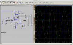
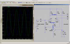
try it in a simulator. I did in a very simple simulator that isnt even meant to deliver any meaningfull numbers but comparing two to each other shows that a CCS improves AC balance quite a bit.
http://tinyurl.com/y9vzn8rc
just take a look at it on the left side is the CCS and right side by the schematic. Hovering over the scopes will highlight the measured components. Not really usefull for any meaningfull numbers but it shows. And every triode there is the exact same parameter all matched all ideal components.
Actually there's not as much difference in simulation between the CCS and just a simple resistor! The high gain of the 12AX7 and the high voltage of 80V cathode to ground make for little change. The biggest problem with the circuit is that the plate voltage on the LTP is too high so that there is not enough positive drive to the EL34's. Dropping the resistor from 82K to 68K or 47K improves the drive a lot. 260v on the plates is much better.
Sorry, just broke the simulation... I agree the constant current sink does appear to improve the balance. I was trying to change the valve gain to see how it performed with a lower gain valve but then I broke it. It does only improve the balance and does not completely cure it and of course there will still be differences in the gain of each half of the double triode and it will not fix that either.
It is very counter-intuitive, but I am now sold on the simplistic conclusion, that with a constant current source the outputs must oppose each other. So exploring this conclusion at the limiting condition of having no gain in one of the triodes, there would be no output (the cathode would follow the grid), whilst a badly matched pair where one triode is nearing cut-off for part of the cycle would show a heavily distorted output on both anodes.
Sorry, just broke the simulation... I agree the constant current sink does appear to improve the balance. I was trying to change the valve gain to see how it performed with a lower gain valve but then I broke it. It does only improve the balance and does not completely cure it and of course there will still be differences in the gain of each half of the double triode and it will not fix that either.
yeah its kind of touchy 😀
took me a few minuts to stabilise that simulation. As I said its not really meant for stuff like this
If you want I can change the mu and gm1 values
- Home
- Amplifiers
- Tubes / Valves
- Testing newly built mullard 5-20
