Actually there's not as much difference in simulation between the CCS and just a simple resistor! The high gain of the 12AX7 and the high voltage of 80V cathode to ground make for little change. The biggest problem with the circuit is that the plate voltage on the LTP is too high so that there is not enough positive drive to the EL34's. Dropping the resistor from 82K to 68K or 47K improves the drive a lot. 260v on the plates is much better.
for the CCS that would mean a 4K2 resistor
and for the non CCS 56K would be the closest value
I had the same problem with the simulation breaking when making changes to test the circuit baudouin0 posted with the LED.Sorry, just broke the simulation... I agree the constant current sink does appear to improve the balance. I was trying to change the valve gain to see how it performed with a lower gain valve but then I broke it. It does only improve the balance and does not completely cure it and of course there will still be differences in the gain of each half of the double triode and it will not fix that either.
I've pulled my tin of semi conductors out of the loft and had a dig through. Ignoring the very large power transistors, these are what I've got that fit the 100V criteria.
2SC2611
2N3440
2SC2229
BF423 - Think hfe may be too low on these
I only had a single BD139 and a single 2N5192.
Dumb question, but if 82K is not the best value for the cathode resistor, why would the engineers at mullard have chosen it?
the 470K resistor into a LED will do 800uA that times 50 and you get your max collector current.
The 10M45S integrated circuit CCS is affordable and easy to configure. I'm guessing the cost will be approx. 2 UKP.
Remember, Mullard publicized the 5-20 to sell items they manufactured.
Remember, Mullard publicized the 5-20 to sell items they manufactured.
The 10M45S integrated circuit CCS is affordable and easy to configure. I'm guessing the cost will be approx. 2 UKP.
Remember, Mullard publicized the 5-20 to sell items they manufactured.
The minimum current of this easy to set up device is by the datasheet 2mA not 1.5-1mA which is what this requires
Running it out of spec can be A:tricky and B:noisy. And I would personally go with the transistor option myself just because quite simply it is simple enough and easy too
Last edited:
Running each section of the 12AX7/ECC83 at 1 mA. for a total of 2 mA. should be acceptable. Another possibility is 'X7 out and 'T7 in. Run the 'T7 triode at 3 mA.
merlin blencow has an excellent chapter in the bookThe minimum current of this easy to set up device is by the datasheet 2mA not 1.5-1mA which is what this requires
Running it out of spec can be A:tricky and B:noisy. And I would personally go with the transistor option myself just because quite simply it is simple enough and easy too
Designing High Fidelity Valve Preamps
where in chapter 6 several pages are spentdiscussing building
current sources aka CCS from discrete components.
see : The Valve Wizard
Running each section of the 12AX7/ECC83 at 1 mA. for a total of 2 mA. should be acceptable. Another possibility is 'X7 out and 'T7 in. Run the 'T7 triode at 3 mA.
1mA each triode is going to drag down the plates quite a bit more. Then the plate voltage will be 200V straight. Lowering the plate resistors would up the plates a bit but then again.....quite a bit of modiffications. Transistor CCS? easier to set up in this case and still keep relatively close to the original thing.
merlin blencow has an excellent chapter in the book
Designing High Fidelity Valve Preamps
where in chapter 6 several pages are spentdiscussing building
current sources aka CCS from discrete components.
see : The Valve Wizard
Yeah hard copy only. For that price I can overengineer something myself. Im sure its a great book but yeah..
So this is with one 12AX7 and 12AT7. The DC is quite different but the AC balance is not far out.

Dumb question, but if 82K is not the best value for the cathode resistor, why would the engineers at mullard have chosen it?
Not dumb at all. I think that by limiting the drive you are preventing blocking distortion on the EL34's. Basically if you can drive more positive than you need, then you will drive the EL34's grids into conduction which will change the voltage across the coupling caps which will drive the DC bias more negative and bias the output stage out of conduction.
Except for that very reason I have increased the cathode bypass cap from 50uF to 470uF because I noticed that very effect on my prototype amplifier and I have fixed by brute force
Except for that very reason I have increased the cathode bypass cap from 50uF to 470uF because I noticed that very effect on my prototype amplifier and I have fixed by brute force
You can help the blocking by increasing R18 and R19 on the grids of the EL34's to say 22k this reduces the amount of current taken if the grids go positive so reducing the increase on voltage on the coupling caps into the grids. Each positive cycle if the grids conduct will increase the voltage across C10 and C11 and reduce your bias causing crossover distortion which take time to recover from.
Last edited:
Currently, I'll stick the LTP CCS on the "to do once it works correctly" list. I'm chasing my tail with voltages not behaving correctly. I think this is the big reason why things are getting pretty ugly with larger signals and at higher frequencies. The waveforms out of V1 and V2 look horrid.
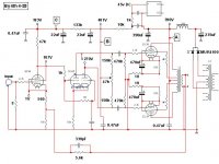
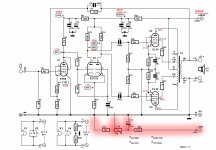
I've redrawn the elektor/clausB schematic as it is implemented in my case along with the voltages I'm getting marked in red. (book figures circled in black) I left the NGV supply in but highlighted in red to indicate it's missing as I'm not sure if it's absence may be playing a part in my V1/V2 anode/cathode voltage issues.
Back when I first started looking the various designs, I obviously saved another schematic relating to the CB 4-30. This one has cathode bias on the output and a few differences in component values. (See Byrith 4-25 attachment) I've no idea where I found it though.
Attachments
Last edited:
Yes your EF86 is taking less current then the schematic would suggest. However I prefer your bias voltages with the V1 plate higher and the V2 plate lower. Looks OK to me. R7 will influence the bias voltage slightly. Don't think your volatage will make that much difference to the horrid signals. I think if your expecting a perfect square wave on V2 you will be dissapointed.
Last edited:
Your ECC83 still looks to me like it's in cutoff, Vgk = 14v. You also posted recently that V2 grids were at different DC V, which was explained on another forum - Mullard 5-20 high DC Voltages - Page 5 - UK Vintage Radio Repair and Restoration Discussion Forum as being a consequence of your DMM Z and the EF86 running at very Ia. I think it's probable V2 is starved of current and hence imbalance, but the two anodes are near in value, starved LTP's usaully have a Va imbalance too.
Could you measure Vgk please, one probe on pin 7/2 the other on pin 8, the result as shown on the schematic should be within 2v of each other. Also suggested putting a 100r or bigger pot in the cathode of V1 and adjusting till V2 Vgk is within spec.
Could be wrong but the waveform out of the LTP looks really off.
Andy.
Your ECC83 still looks to me like it's in cutoff, Vgk = 14v. You also posted recently that V2 grids were at different DC V, which was explained on another forum - Mullard 5-20 high DC Voltages - Page 5 - UK Vintage Radio Repair and Restoration Discussion Forum as being a consequence of your DMM Z and the EF86 running at very Ia. I think it's probable V2 is starved of current and hence imbalance, but the two anodes are near in value, starved LTP's usaully have a Va imbalance too.
Could you measure Vgk please, one probe on pin 7/2 the other on pin 8, the result as shown on the schematic should be within 2v of each other. Also suggested putting a 100r or bigger pot in the cathode of V1 and adjusting till V2 Vgk is within spec.
Could be wrong but the waveform out of the LTP looks really off.
Andy.
Oh yep that cannot be right with Vgk of 14v and yet a sensible plate voltage. You do have a 12AX7 fitted?
I will measure it again as you describe above. All previous measurements have been made relative to ground. I now also have a x100 scope probe with 100M input impedance which I can use on the higher impedance sections.Your ECC83 still looks to me like it's in cutoff, Vgk = 14v. You also posted recently that V2 grids were at different DC V, which was explained on another forum - Mullard 5-20 high DC Voltages - Page 5 - UK Vintage Radio Repair and Restoration Discussion Forum as being a consequence of your DMM Z and the EF86 running at very Ia. I think it's probable V2 is starved of current and hence imbalance, but the two anodes are near in value, starved LTP's usaully have a Va imbalance too.
Could you measure Vgk please, one probe on pin 7/2 the other on pin 8, the result as shown on the schematic should be within 2v of each other. Also suggested putting a 100r or bigger pot in the cathode of V1 and adjusting till V2 Vgk is within spec.
Could be wrong but the waveform out of the LTP looks really off.
Andy.
Oh yep that cannot be right with Vgk of 14v and yet a sensible plate voltage. You do have a 12AX7 fitted?
Yes definitely a 12AX7 fitted. The only other valves I have used are 5751's. I do have both an ECC81 and ECC82 but I've not tried either as they aren't drop in swaps.
These are a few of the nasty waveforms I captured yesterday. Feedback is connected to the 8R tap and has the values 3.3K and 560pF
100Hz 610mV in - Output vs 12AX7 plate (x100 probe on CH2)

1KHz 600mV in - Output vs 12AX7 plate (x100 probe on CH2)

This is a 1Khz square wave captured at the plate of EF86. No idea why the spike is so large. (x100 probe)

- Home
- Amplifiers
- Tubes / Valves
- Testing newly built mullard 5-20