The wooden chassis is only temporary to prove whether or not the layout and tag board arrangement works. It will be reassembled onto nicely machined aluminium panels as a pair when I finish with the fiddling. I've considered the EF86 as triode mod as that's likely to be the only change I would consider making.Firstly, your have made a neat job, but personally I would use metal rather than wood. Both fire risk and also shielding from main hum and other external interference.
Secondly you should look at the following site "30W Push Pull amplifier designed by Claus Byrith". It can be accessed from the Lundhal transformer site.
Claus uses the Mullard 5-20 as the base of his design but makes some nice changes including reducing feedback, operating the EF86 as a triode and reducing the standing current in the EL34's.
I like to run output valves, in my designs, at 80% of their power rating. Your current operating point is above valve spec
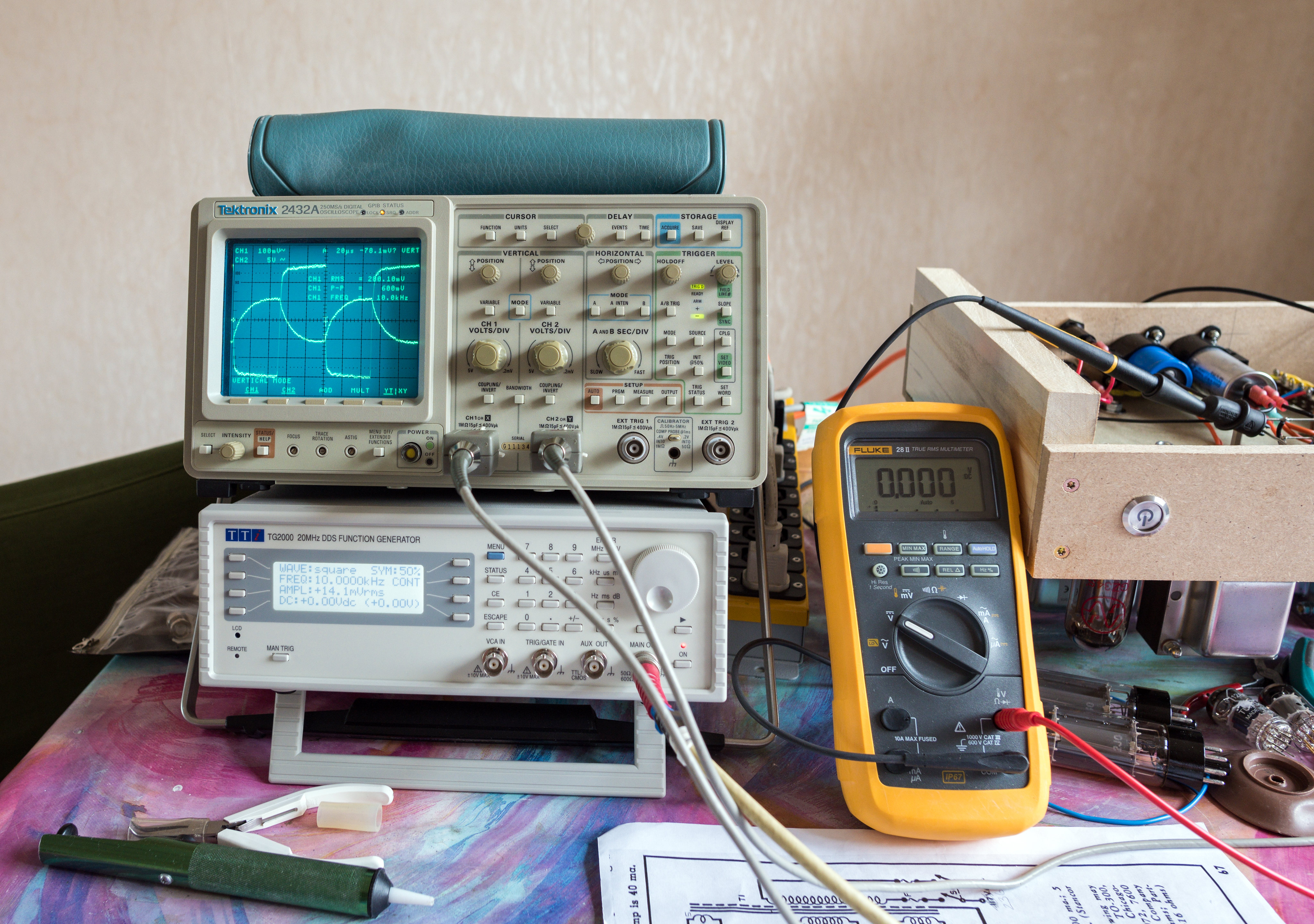
I've left the voltage levels as they are for now and am concentrating on the task of testing stability. Testing with the amp in open loop, phase inversion from the output transformer appears to occur around 70KHz. (these are the outputs I have used. Though, like a dunce, I opted for the 4-8-16 ohm tapped secondary which has narrower bandwidth. (claims 20Hz-40KHz in the sheet supplied)

In testing with the amp, I've noticed two cases that cause it to oscillate. Sub sonic frequencies, particularly at higher power levels trigger it which I guess is best off being filtered at the input using a 0.0068-0.01uF capacitor from the socket to R2. (As per Eli's suggestion) I'm guessing that they didn't include this in the original design as the pre-amps of the time did it instead.
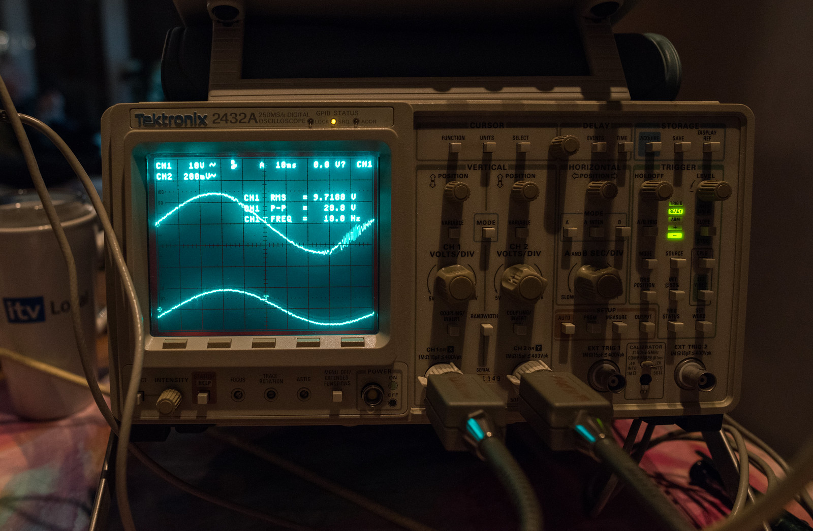
Stable at 8.88Vrms

Starts to oscillate by 9.7Vrms
One other thing that I noticed in experimenting with the feedback network is that the ringing observed with square waves is virtually eliminated by removing the step network on the anode of V1. (C1 & R3) I tried altering the values of these two components just to see what their effect was but even upping R3 to 10K and C1 to 220pF didn't seem to yield any obvious difference.
1KHz standard feedback/step components (top trace is output, bottom trace is input on all these shots with two traces)
An externally hosted image should be here but it was not working when we last tested it.
1KHz standard feedback but no step network

10KHz standard
An externally hosted image should be here but it was not working when we last tested it.
10KHz no step network

For the most part, it does seem to be stable and it's only when pushing the power to the limit under normal circumstances that cause problems, where it seems to ring rather than clip.

I've put a few graphs together showing how the output behaves with respect to a fixed input signal voltage across the frequency range here.
Performance Charts - Google Sheets
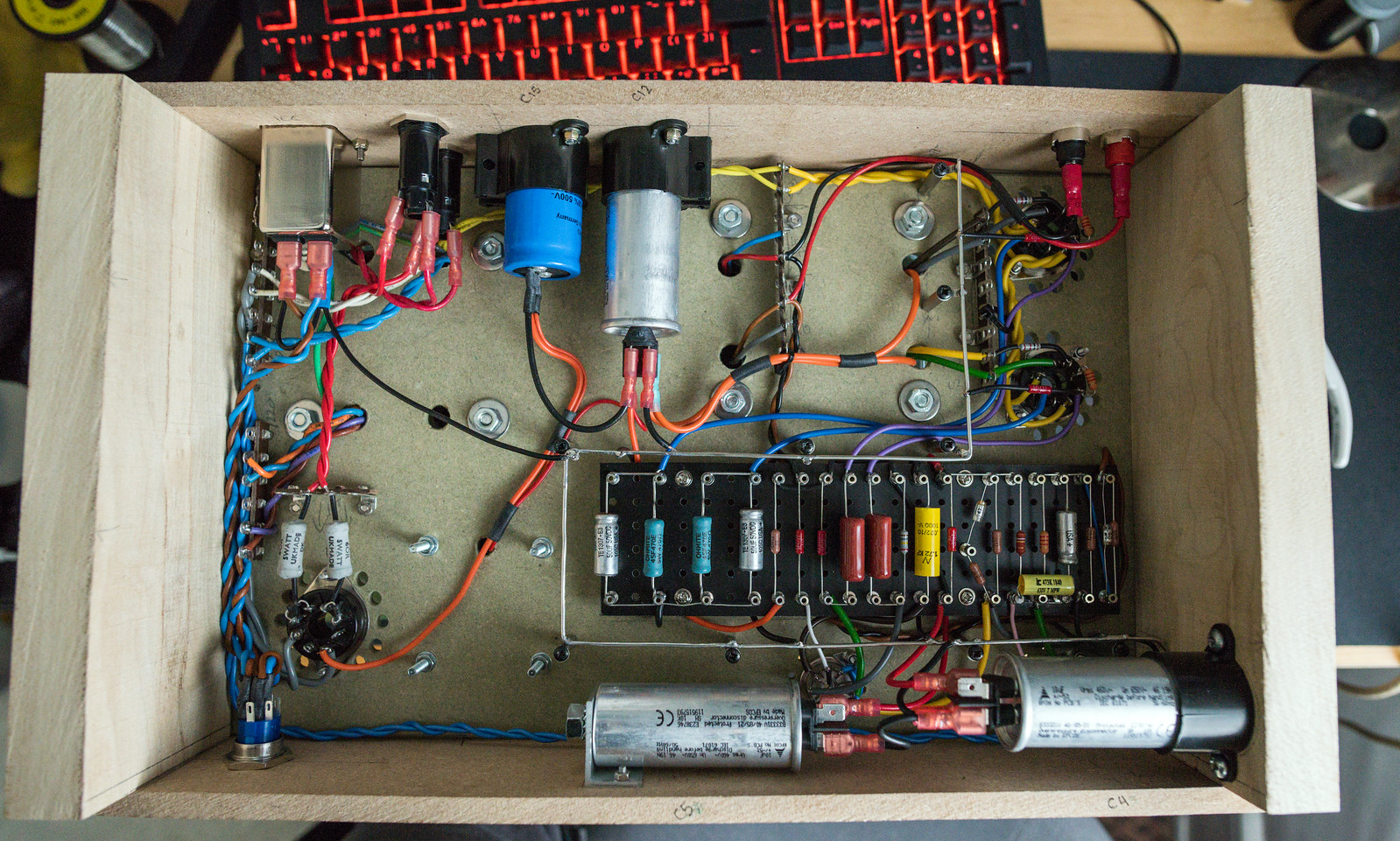
I decided that I would probably end up sinking more time than necessary trying to debug the amp when the most likely cause of the problems was the layout. So, the Mk 2 Version, when all else fails, do it by the book. This is pretty much as close to the book layout as I can get. I've left the chassis about 1.5" wider as this will give me room for some wooden supports without affecting internal space. I've kept the component locations within a mm or two of their original positions and the valve sockets are orientated exactly as per the book. The capacitors may create some fun with the wiring but I don't think it'll be far off standard. The two capacitors that live between the 9 pin valves will be the hardest as it's supposed to be a multi-element electrolytic which I don't have. I chose to go with a pair of 10uF MKP caps originally so I foresee either some major fiddling or me buying a multi-element cap. I also see me having to trim the tag board as it's a bit wide and tall to fit in and permit space to run a ground bus around.
The connections to the output transformer from the output valves in the standard design are significantly shorter and the B+ runs in the opposite direction too. (I have a sneaking suspicion that this may be a big contributor to the stability issues I was having in the Mk1) I'm also planning on connecting up the mains switch this time. I may even rectify the one 6.3V heater line in order to get the power LED to work too. (Though I'll probably save that for when I prove if it works stably or not)
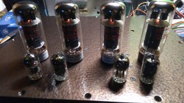
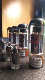
In other news, I picked up a set of spare valves that I could use whilst I'm testing and fiddling. That saves wearing out the vintage GE's or cooking the more expensive stuff. I got some JJ KT77's which actually seem to run better than the Tung-Sol EL34B's. I fitted that 0.01uF cap on the input which prevented oscillation in the LF and just left it play all day yesterday. Worked great for about 7 hours without any signs of stress or any glowing plates and sounded great too. Clearly the Mk1 was conditionally stable.
An externally hosted image should be here but it was not working when we last tested it.
The connections to the output transformer from the output valves in the standard design are significantly shorter and the B+ runs in the opposite direction too. (I have a sneaking suspicion that this may be a big contributor to the stability issues I was having in the Mk1) I'm also planning on connecting up the mains switch this time. I may even rectify the one 6.3V heater line in order to get the power LED to work too. (Though I'll probably save that for when I prove if it works stably or not)
An externally hosted image should be here but it was not working when we last tested it.
In other news, I picked up a set of spare valves that I could use whilst I'm testing and fiddling. That saves wearing out the vintage GE's or cooking the more expensive stuff. I got some JJ KT77's which actually seem to run better than the Tung-Sol EL34B's. I fitted that 0.01uF cap on the input which prevented oscillation in the LF and just left it play all day yesterday. Worked great for about 7 hours without any signs of stress or any glowing plates and sounded great too. Clearly the Mk1 was conditionally stable.
Been a while since I posted on this. Mk2 built using the second set of components performed almost identically to Mk1 proving that clearly my homebrew layout wasn't an issue after all.
This is how the layout turned out.
Having gotten a little annoyed with it, I decided to convert the front end to the claus byrith modified version with EF86 triode strapped. I managed to make the changes without having to buy anything as I already had the necessary components to do it. Things have improved considerably, particularly the stability. It now takes a much larger input voltage for full output which is definitely preferable.

These were the tests done today. I realised afterwards that I forgot to solder the link from C2 to the bus bar in my diagram above. I also didn't have a 560pF cap to hand so used a pair of 270pF in parallel to make 540pF. I need to take some measurements tomorrow and see what the voltages around the EF86 and phase splitter are as I've made no other changes yet. As an experiment, I also tried using the 16 ohm tap for the feedback.
8 Ohm feedback tap with 8 ohm dummy load
16 ohm feedback tap with 8 ohm dummy load (load on 8 ohm tap)
Open Loop
There are still some odd issues with HF that need sorting as the power output before distortion sets in at 20KHz is poor. I think the phase shift seems quite high from what I can see on the scope.
This is how the layout turned out.
An externally hosted image should be here but it was not working when we last tested it.
Having gotten a little annoyed with it, I decided to convert the front end to the claus byrith modified version with EF86 triode strapped. I managed to make the changes without having to buy anything as I already had the necessary components to do it. Things have improved considerably, particularly the stability. It now takes a much larger input voltage for full output which is definitely preferable.
An externally hosted image should be here but it was not working when we last tested it.
These were the tests done today. I realised afterwards that I forgot to solder the link from C2 to the bus bar in my diagram above. I also didn't have a 560pF cap to hand so used a pair of 270pF in parallel to make 540pF. I need to take some measurements tomorrow and see what the voltages around the EF86 and phase splitter are as I've made no other changes yet. As an experiment, I also tried using the 16 ohm tap for the feedback.
8 Ohm feedback tap with 8 ohm dummy load
16 ohm feedback tap with 8 ohm dummy load (load on 8 ohm tap)
Open Loop
There are still some odd issues with HF that need sorting as the power output before distortion sets in at 20KHz is poor. I think the phase shift seems quite high from what I can see on the scope.
Last edited:
Just some suggestions. (Electrolytic capacitors have come a distance since the 1960) I would check the values for C4 and C5 and increase these from 10uf to those used in Claus design ie 47uf or 100uf. Likewise, I would increase C13 and C14 to 220uf or 470uf.
Where are R18 and R19, I cannot see them in your photos, they may be correctly placed but just check. They need to be right next to the pins on the Socket as close as possible. I would also increase the value of these from 2k2 to 3k3 or 4k7. I built this design some 20 years ago and found that this increase was beneficial in suppressing oscillation.
Finally, the value of C9 (470pf) is very transformer dependant and you may find that this needs some experimentation. If I remember correctly there is a good article on stability on this site that covers this.
I suspected this would happen. It really is by design not the wiring itself. You have to keep in mind this amp was one of the first ones to use this kind of phase inversion and the pentode as input amplifier. So minor details (problems) are expected.
I dont really know what you want to achieve here. First of all in your previous posts you stated you dont want to deviate from the original schematic and then you go arround removing capacitors and resistors and eventually strapping the pentode into triode mode. Thats quite the deviation.
As much as you want to improve stabillity and distortion on the amplifier you really wont achieve your desired results unless you design a amplifier from ground up completely scratch to meet your demands.
This is just a thought: if you really want to narrow down where does your distortion come from (or the square wave response) I suggest disconnecting NFB and the go tube by tube AC couple to anodes, grids and cathodes and find out where it comes from specifficaly.
Here Ill send some pictures of my approach to this amplifier 🙂. All tho I am a PCB nerd I definitely apprechiate the beautyfull work of yours actually making the thing work and look very neat with the turret board. I also included my prototype so you can at least see how the layout looks like. The white board is double sided and I am using one side as a shield (no current running trough it just as a shield.
I actually didnt have the change to measure performance of my amplifier with a scope and frequency generator but at least from the hours of listening it seems just okay. I may need to to tweak the NFB capacitor aswell because I am using toroidal outputs which is quite different from the original. I will eventually measure my amplifier just got have time for it aswell 🙂
Attachments
-
 P_20200411_210753.jpg891.9 KB · Views: 203
 -
 photo_2020-05-05_11-59-33.jpg57.8 KB · Views: 177
 -
 photo_2020-05-05_11-59-29.jpg122.2 KB · Views: 166
 -
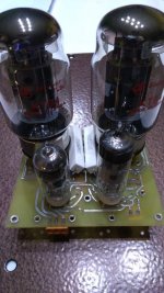 photo_2020-05-05_11-59-31.jpg132.2 KB · Views: 169
 -
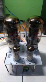 photo_2020-05-05_11-59-34.jpg110.9 KB · Views: 186
 -
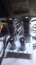 photo_2020-05-05_11-59-59.jpg114.1 KB · Views: 211
 -
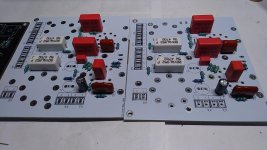 photo_2020-05-05_12-00-12.jpg113.7 KB · Views: 209
 -
 photo_2020-05-05_12-00-15.jpg104.5 KB · Views: 197
 -
 P_20200411_210704.jpg575.3 KB · Views: 199
Last edited:
R18 & 19 are on the valve sockets. C4 has been increased to 47uF as I had the one from the first build but don't have any more to do the others. Doesn't increasing those cathode capacitors increase the likelihood of LF instability when global NFB is used?Just some suggestions. (Electrolytic capacitors have come a distance since the 1960) I would check the values for C4 and C5 and increase these from 10uf to those used in Claus design ie 47uf or 100uf. Likewise, I would increase C13 and C14 to 220uf or 470uf.
Where are R18 and R19, I cannot see them in your photos, they may be correctly placed but just check. They need to be right next to the pins on the Socket as close as possible. I would also increase the value of these from 2k2 to 3k3 or 4k7. I built this design some 20 years ago and found that this increase was beneficial in suppressing oscillation.
Finally, the value of C9 (470pf) is very transformer dependant and you may find that this needs some experimentation. If I remember correctly there is a good article on stability on this site that covers this.
Lets just say I wanted to build as standard, get it working properly and then go on the usual quest for improvement. The Claus Byrith front end mod was first on my list of things to try out as reduced loop gain was preferable as I don't need the gain so I would benefit from improved noise performance. Your build looks very good. The great benefit to the pcb's is that everything is tidy and you can't get your wiring wrong so easily. To be fair, mine sounded good when tested with music, but doesn't test well. I still feel that the wooden prototype chassis is leading to some false issues so I'm looking into building a replacement top panel with some aluminium I have.I suspected this would happen. It really is by design not the wiring itself. You have to keep in mind this amp was one of the first ones to use this kind of phase inversion and the pentode as input amplifier. So minor details (problems) are expected.
I dont really know what you want to achieve here. First of all in your previous posts you stated you dont want to deviate from the original schematic and then you go arround removing capacitors and resistors and eventually strapping the pentode into triode mode. Thats quite the deviation.
As much as you want to improve stabillity and distortion on the amplifier you really wont achieve your desired results unless you design a amplifier from ground up completely scratch to meet your demands.
This is just a thought: if you really want to narrow down where does your distortion come from (or the square wave response) I suggest disconnecting NFB and the go tube by tube AC couple to anodes, grids and cathodes and find out where it comes from specifficaly.
Here Ill send some pictures of my approach to this amplifier 🙂. All tho I am a PCB nerd I definitely apprechiate the beautyfull work of yours actually making the thing work and look very neat with the turret board. I also included my prototype so you can at least see how the layout looks like. The white board is double sided and I am using one side as a shield (no current running trough it just as a shield.
I actually didnt have the change to measure performance of my amplifier with a scope and frequency generator but at least from the hours of listening it seems just okay. I may need to to tweak the NFB capacitor aswell because I am using toroidal outputs which is quite different from the original. I will eventually measure my amplifier just got have time for it aswell 🙂
I did some open loop testing during my lunch break, following the input signal through the amp using 10K square to find where it distorts. Output from EF86 plate looks clean enough into the grids of 12AX7/5751. Out of the plates of the phase splitter it looks like a shark fin.
10KHz SQ - EF86 out Vs 12AX7 out - Open Loop
10KHz SQ - 12AX7 plates - Open Loop

DC conditions measured with HT at 385Vac at the rectifier
C15 - 452
C12 - 438
C5 - 409
C4 - 116
V1
A - 57
K - 0.54
G - 0
V2
A1 - 337
A2 - 336
G1 - 56.9
G2 - 51.9
K - 60.8
V3
A - 427
K - 30.1
SG - 425
V4
A - 427
K - 29.9
SG - 426
well....Now we know where most of the distortion comes from: the phase inverter. I cant think of a single reason why it is happening... Try and pull out the output tubes and measure the signal again. Also take a look at the other grid of the 12AX7 (the one with the 1M and capacitor). I have one last idea and that is to use a CCS in the cathodes. Like a N channel depletion mosfet and set it for 1mA. Other than that you can try just to see what would little cappactiance do put a 200pF cap across the 82k resistor. It may induce oscillation so do it into a dummy load
Tried the above suggestion with no output valves fitted. I also swapped out the 5751 valve for a 12AX7 just in case. Voltages were extremely high as expected.
This is the grid of the PI vs the plate
 [/url]
I repeated the earlier test just to make sure the 12AX7 behaved the same as the 5751.

This is the grid of the PI vs the plate
I repeated the earlier test just to make sure the 12AX7 behaved the same as the 5751.
so with the power tubes out same result. Could you also take a look at the cathodes of the 12AX7. And try and bypass the 87k resistor with a 100-200pF capacitor
Not the same result with the power valves removed. What went into the grid of the PI came out clean without the power valves. There is a slight change but nothing like it was with the power valves in place. I put the power valves back in and double checked to make sure it was still bad with them in. (second picture)so with the power tubes out same result. Could you also take a look at the cathodes of the 12AX7. And try and bypass the 87k resistor with a 100-200pF capacitor
In the first picture above, CH1 is the one grid of 12AX7 and CH2 is the one anode.
Oh alright that makes sense now. I think you might want to buy a 12AU7 at this point. Being a 12AX7 a very high impedance tube indeed it might have a sligh problem driving a capacitive load (yes the grids of the tubes as crazy as it sounds that little cappacitance may be limiting you) so get a 12au7 mod the resisistors to something more reallistic (if you want just copy any old 6SN7 long tail inverter like from a EICO HF50 or something like that) and a that point I think you have rather low gain and you could return back to a pentode configuration in the preamp EF86.
Thats just my thoughts tho. I did have a feeling in my gut that it might be happening because of the parasitics inside the tubes and you know that sharp sharp sharp corner is quite a "high frequency". The cappacitances of the tubes themselves are your limit then.
Interestingly if you get all this sorted out you know..the preamp is relatively square the output of the inverter is basically almost copy and paste and if you manage to get the same results to go into the power tubes then you will be truly limited by the output transformer. I do have a 12BH7 on hand which is very low gain compared to the 12AX7 and actually the gain of the inverte is roughly 25 so the BH is exactly on edge 25. I do suggest however to replace the 12AX7 with a 12AU7 and just use the values of a EICO HF50 (the 12AU7 is essentially a noval 6SN7) and that should get you more drive strenght. Lower output impedance of the inverter should supress the effect of parasitics from the power tubes. I wonder if you disconnect the heaters of the power tubes and let them just chill out in the circuit (with HV on the plates and cathode hooked up) if the issue would still persist. If yes but less apparent then I am almost certain thats your issue here. The parasitics. Btw when the tube is cold you have just a vacuum capacitor so no other factors can interfere with your measurements. But its more than likely that its cause by the very very very high impedance of the inverter/driver. Get a 12AU7 and change the values to of a EICO HF50 in the inverter and it should give you much sharper results
Also if you think of it some amplifiers have a capacitor in the primary of the output transformers to dampen high frequencies. Maybe thats why they did not have to do it here because the flaw in the inverter didnt really allow any too high frequencies trough anyways. So in a way you just removed a component and saved a penny each amplifier made
Im sorry for the grammar here its almost midnight and I can barely see the screen 😀 .
So yeah at this point my only idea is to make the phase splitter out of a 12AU7 with not much gain at all and get the EF86 to be your workhorse in terms of amplification. Use that EF86 when you have it..
Can you post your current Schematic. The Phase spliter looks like its voltages are somewhat out but it would be good to see your actual circuit. I note that Claus had 170Volts for the Triode EF86 and your have 116volts. Hence 57 volts on V1 Plate and 60Volts on Cathode of Phase Spliter. This means that the phase spliter cathode is too low a voltage and not conducting enough
Can you post your current Schematic. The Phase spliter looks like its voltages are somewhat out but it would be good to see your actual circuit. I note that Claus had 170Volts for the Triode EF86 and your have 116volts. Hence 57 volts on V1 Plate and 60Volts on Cathode of Phase Spliter. This means that the phase spliter cathode is too low a voltage and not conducting enough
On my amplifiers I have measured 70V on the anode of the EF86 at 420VDC as power supply. It could be that but I find it unlikely. Its just a design quirk of this amplifier itself. Using a 12AX7 as inverter and driver at the same time is kind of asking for trouble. The very high impedance of the tube makes it not really ideal for this job. One other solution would be to add a buffer with some sort of a beefier tube like a 12AU7 or 12BH7 (to make it a proper strong drive) but at that point youre adding another tube to the circuit when it could be done easier and use a 12AU7 in the inverter and mod the values and just go with the reduced gain (not if it would matter much cause the EF86 has lots of it) and larger input signal capabillity would be more desireable always. Unless youre hooking a crystal pickup direct up to the amplifier.
This is how things sit currently. The front end to the grid of 12AX7 follows the CB design. I also get the feeling that the voltages aren’t correct. I’m pretty sure the documentation says that the direct coupled LTP is quite sensitive to operating point.Can you post your current Schematic. The Phase spliter looks like its voltages are somewhat out but it would be good to see your actual circuit. I note that Claus had 170Volts for the Triode EF86 and your have 116volts. Hence 57 volts on V1 Plate and 60Volts on Cathode of Phase Spliter. This means that the phase spliter cathode is too low a voltage and not conducting enough
The leak tl25 I’ve also been looking at is similar insofar as they opted for a ECC81/12AT7 instead of ECC83/12AX7. In an ideal world, it would be nice to figure out why something that is known to work isn’t working in my case. The budget on this project has really gone into orbit so I’m really trying to avoid additional spending on things I’d already bought for the time being. It’s looking like I’ll need to buy some metal working tools or get my cnc metal plates made to debunk the idea that the wooden test chassis is playing a big part in all this chaos. Changing that valve out is something that I will look into at some point because it’s so commonly pointed out how poor a choice it was. I’ll have another dog through my components stash and see if I have the necessary values to make the change though. If something like a jj can be bought dirt cheap I may give it a try. I do appreciate all the help you’ve given me. I won’t deny that the whole project has started to annoy me with its antics what with the rather extreme cost of it so far.So yeah at this point my only idea is to make the phase splitter out of a 12AU7 with not much gain at all and get the EF86 to be your workhorse in terms of amplification. Use that EF86 when you have it..
Last edited:
As the phase inverter is direct coupled to the EF86 plate , the voltage of that plate has to be at an appropriate level.
By triode connecting the EF86 this level is wrong. Do rewire the EF86 as
per mullard original and see if things straighten up.
Also the use of ECC83/12AX7 : as the symmetry of the phase inverter depends on
the tubes mu, using an ECC81/82 will reduce the amplification and thus increase the
inherent unbalance of a LTP.
Last edited:
Yes, the voltages of the LTP are completely dependent on the preceding EF86 stage. It is both a strength and weakness of this direct (no capacitor) connection. You must get the ECC83 cathode voltage correct as per the original Mullard spec to ensure that the LTP is conducting the correct current. Vary R4 until voltages are correct.
It’s looking like I’ll need to buy some metal working tools or get my cnc metal plates made ...
It is possible to get buy with a minimum set of tools, at least as a proof of concept. Many here use step drills to make large holes in metal, but I found rapid-online to be very cheap for sheet metal punches, and it make a very professional looking end product.
Sheet metal punches
Then any sturdy piece of sheet metal can be used for a chassis, although the consensus here is for 2mm or 2.5mm aluminium. I like the idea of 'repurposing' and I found a perfectly good base for a chassis in my local recycling (an old roasting dish), and I have also bought solid baking tins in 2nd hand shops.
However, the layout needs to be planned carefully and mistakes cannot be rectified, so it ends up being the part that soaks up the most time, detracting from the fun with the soldering iron. Wood is a lot easier for prototyping.
(I tried to edit and get it the right way up, but you get the drift ...)
Attachments

Last edited:
Folks, let us never forget that Mullard published the 5-20 design to sell stuff they manufactured. The topology is good, but some of the implementation details are not.
Asking the wimpy triode found in the 12AX7/ECC83 to drive the CMiller of a UL mode EL34 is not good.
Identical LTP plate load resistors (R11/R12) works only when the tail load (R6) is sufficiently large and, at 82 Kohms, it's not. Fortunately, this is easily remedied by replacing the resistor with a 10M45S constant current sink (CCS). CCS loading LTP tails forces symmetry between the 2 sides and allows medium μ types to work very well. Sometimes, things "play out" to require connection of the CCS to a "short" negative rail, instead of ground.
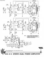
For purposes of comparison, I'm providing the schematic of EICO's HF87. The signal topology is the same as used in the 5-20, but implementation details differ.
Asking the wimpy triode found in the 12AX7/ECC83 to drive the CMiller of a UL mode EL34 is not good.
Identical LTP plate load resistors (R11/R12) works only when the tail load (R6) is sufficiently large and, at 82 Kohms, it's not. Fortunately, this is easily remedied by replacing the resistor with a 10M45S constant current sink (CCS). CCS loading LTP tails forces symmetry between the 2 sides and allows medium μ types to work very well. Sometimes, things "play out" to require connection of the CCS to a "short" negative rail, instead of ground.
For purposes of comparison, I'm providing the schematic of EICO's HF87. The signal topology is the same as used in the 5-20, but implementation details differ.
Attachments
- Home
- Amplifiers
- Tubes / Valves
- Testing newly built mullard 5-20