Kei,
Please remind us of the DC resistance of the choke you used. Original was spec'ed at 200 ohms.
And the value of the first smoother cap C15 in the Mullard book.
Please remind us of the DC resistance of the choke you used. Original was spec'ed at 200 ohms.
And the value of the first smoother cap C15 in the Mullard book.
......According to the mullard spec, this should be 410Vac going in. I'm seeing 406Vac. Once rectified, I can't see how I can get higher than their book figures if I have a lower voltage going in.
I assume the SS diode mod used to prevent arc over in the 5AR4 wouldn't be able to cause the increased rectified voltages i'm seeing.
Your B+ is too high based on your Vac secondary voltage. You provided new info (new to me), the SS diodes in the rectification circuit. Now I guess is there is an error in the way the SS diodes are wired and you are getting the SS diodes to rectify, rather than the 5AR4, so you don’t have the expected voltage drop due to the tube rectification. Check that first. If that checks it would also be helpful to know the details of you choke as Alan asked, as well as the rest of your power supply components. Have you tried to simulate your PS using Duncan’s PSUD2 program?
Goodluck.
Last edited:
The choke used is a VVT VTL12158-1440 . They quote it as suitable for a mono mullard 5-20. I've measured the resistance on the one I've not used at 117.5 ohms. Perhaps this may explain why things are a little askew after the choke.Kei,
Please remind us of the DC resistance of the choke you used. Original was spec'ed at 200 ohms.
And the value of the first smoother cap C15 in the Mullard book.
As suggested by yourself in my planning thread, I upped the value of C15 to 47uF.
I'm certain the diodes have been used correctly as I get no B+ with the rectifying valve removed. When the valve is fitted, B+ slowly rises as the valve heats up as expected. I followed this guide posted by Eli as a way of avoiding the likelihood of the sovtek 5AR4 arcing over. The only change I made was to move the cathode of the one diode from pin 5 to pin 3 as it suited my layout better.Your B+ is too high based on your Vac secondary voltage. You provided new info (new to me), the SS diodes in the rectification circuit. Now I guess is there is an error in the way the SS diodes are wired and you are getting the SS diodes to rectify, rather than the 5AR4, so you don’t have the expected voltage drop due to the tube rectification. Check that first. If that checks it would also be helpful to know the details of you choke as Alan asked, as well as the rest of your power supply components. Have you tried to simulate your PS using Duncan’s PSUD2 program?
Goodluck.
This was the PSUD simulation I performed in the planning phase.
As someone who built Mullard 5-20's in about 1965 using A&R 4014 output transformers, may I offer the following comments about the audio qualities of the design.
Several friends who also built their own amplifiers allowed me to replace the Williiamson designed amps for a comparison of the sound. One commented "It sounds like a Mullard"; he was referring to the rather harsh upper middle of class AB tetrode vs class A triode. Part of the trouble is the EF86 first stage (cf Radford design) and the EL34's running UL for higher output. Anyway good luck, you may like the sound.
Several friends who also built their own amplifiers allowed me to replace the Williiamson designed amps for a comparison of the sound. One commented "It sounds like a Mullard"; he was referring to the rather harsh upper middle of class AB tetrode vs class A triode. Part of the trouble is the EF86 first stage (cf Radford design) and the EL34's running UL for higher output. Anyway good luck, you may like the sound.
The choke used is a VVT VTL12158-1440 . They quote it as suitable for a mono mullard 5-20. I've measured the resistance on the one I've not used at 117.5 ohms. Perhaps this may explain why things are a little askew after the choke.
As suggested by yourself in my planning thread, I upped the value of C15 to 47uF.
A few things spring to mind.
First the AC voltage measurements are some times a little different using a digital meter vs an coil meter. And as you say the digital meter will show a slightly higher DC voltage from the AVO (likely 10M ohms vs 1000 ohms per volt.)
The voltages in post #9 round the choke do correspond to to the correct current draw, aprox 130mA with a 15 volt drop, so adding another 100 ohms would drop you nearly 28 volts in total and get close to 445 volts on C12?
You might also loose a volt or two if you put the 10uF cap in C15 position and the 47uF in C12. As audiowise suggests.
What you need to measure next is the voltage on the anodes of the EL34s and see what voltage drop the output transformer gives. It was about 10 volts in the Mullard specs. Then you can work out the dissipation of the output pair... As was mentioned before I think, the original design does run them at (or very slightly over) their design limit.
After all that you still might want to slightly increase the value of the 470 ohm cathode resistors (R20/21 or R17/18 depending on which diagram you use) to further improve their life expectation.
Alan
The voltages in post #9 round the choke do correspond to to the correct current draw, aprox 130mA with a 15 volt drop, so adding another 100 ohms would drop you nearly 28 volts in total and get close to 445 volts on C12?
You might also loose a volt or two if you put the 10uF cap in C15 position and the 47uF in C12. As audiowise suggests.
What you need to measure next is the voltage on the anodes of the EL34s and see what voltage drop the output transformer gives. It was about 10 volts in the Mullard specs.
Alan
Alan, when you wrote “100 ohms would drop nearly 28 V”, did you mean both R23 & R24 at 100 in the schematic in post #6. If both are used it will give you ~28V reduction, and that will likely fix the overvoltage problem. I was wondering why Kei did not use them, or did you?
Kei, I also tried to understand your PSUD2 results, of which I’m no expert. Could you explain why it shows 290V at the transformer secondaries in the graphic, where I expected to see a value closer to the actual transformer secondary output voltage (adjusted for the load). Before changing values of C12 and C13 and adding R23 and R24 a new simulation would be good.
Thanks for the info Alan. I've done some measurements following the info in the mullard book itself.
No input signal sat idle.
Mains voltage - 237.6Vac
HT voltage - 398.5Vac (directly measured off the 410-0-410 winding)
C15 - 481Vdc
C12 - 465Vdc
C5 - 431Vdc
C4 - 172Vdc
V4 Anode - 457Vdc
V4 G1 - 0.9Vdc
V4 G2 - 454Vdc
V4 G3/Cathode - 32.7Vdc
Heater - 5.74Vac
V3 Anode - 455Vdc
V3 G1 - 0.6Vdc
V3 G2 - 454Vdc
V3 G3/Cathode - 32.2Vdc
Heater - 5.76Vac
V2 Anode 1 - 317Vdc
V2 Anode 2 - 317Vdc
V2 G1 - 83.5Vdc
V2 G2 - 91.6Vdc
V2 Cathode 1&2 - 96Vdc
V1 Anode - 91.7Vdc
V1 G1 - 0 (no input)
V1 G2 - 114.5Vdc
V1 G3/Cathode - 2.18Vdc
Heater - 5.9Vac
Rect pin 8 - 478Vdc
Rect pin 8 - 5.4Vac (to GND)
Rect pin 2 - 7.2Vac (to GND)
Other measurements I made whilst it was running:
14.5Vrms output is about the limit before it seems to begin to oscillate. (1KHz sine wave showing ringing around the edges of the peaks/troughs). The waveform doesn't flatten off top/bottom like I would have expected, it keeps rising with ringing around the I added 30pF to the feedback capacitance. (making C9 360pF) The ringing on square wave input appears unchanged.
Output level appears to rise below 9Hz and above 42KHz.
Attachments
A GNFB loop is present. Protect the O/P transformer against core saturation by filtering infrasonic noise out at the I/P. A 0.01 μF. cap., instead of a wire, connecting the RCA jack's center pin to the 1 MOhm grid to ground resistance does the trick. The high pass pole formed "corners" at 15.9 Hz.
C9 is a phase compensation part that has to be tuned to the specific O/P "iron" being employed. Drive the amp with a 2 KHz. square wave and adjust that part's value for the best look on an o'scope. It's a compromise between ringing, tilt, and overshoot.
C9 is a phase compensation part that has to be tuned to the specific O/P "iron" being employed. Drive the amp with a 2 KHz. square wave and adjust that part's value for the best look on an o'scope. It's a compromise between ringing, tilt, and overshoot.
Alan, when you wrote “100 ohms would drop nearly 28 V”, did you mean both R23 & R24 at 100 in the schematic in post #6. If both are used it will give you ~28V reduction, and that will likely fix the overvoltage problem. I was wondering why Kei did not use them, or did you?
Kei, I also tried to understand your PSUD2 results, of which I’m no expert. Could you explain why it shows 290V at the transformer secondaries in the graphic, where I expected to see a value closer to the actual transformer secondary output voltage (adjusted for the load). Before changing values of C12 and C13 and adding R23 and R24 a new simulation would be good.
I did not use R23/R24 as the book suggests that the values depend on mains transformer. Since my HT voltages before the rectifier are already lower than their book values by 4V off load and 12V with load, they shouldn't be necessary.
My PSUD2 transformer voltage was set based on 410V x 0.707 = *289.87 to get RMS voltage. If I put 410V in for the transformer, the simulation is way off as i get voltages in excess of 570V.
I have built a stereo set of these amps swell. However I do have a stable 420V power supply. The red plating wont disappear with your EL34Bs. If you play the amplifier at FULL BORE the red plating goes away. Youre pushing way too much voltage into the amp.
My experience is that EL34Bs wont last much here. I run the amp at the intended 420V (stabilised because of the nature of the power supply) and if the amplifier is just sitting there quiet or low volume in the dark you can still see slight red plating on the EL34B where the plates are welded together.
EL34Ls hoever dont show this at all. You might have better luck with them and you wont even need to adapt the power supply section. I ran my amp at 450V all day with EL34L's and nothing out of ordinary was visible at all. And for argument sake I was using the shuguang EL34L. Not the best yet it works flawlessly. Changing over to the 34L's will make your life a little easier.
Slight observation: after about half a year of daily use (4 hours a day average) I began to notice that one of the grids in both tubes is glowing orange in some spots rather bright but that was literary after abusing the amplifier to its max for half a year. The tubes still work great and voltages are right. (From what I could see it was G3 being funky)
If you insist on using the 34B I suggest what the others do- decrease C15 all tho I would rather so you can cheat a little with a zener in series after the choke. I know the thought of having a SINGLE semiconductor in the amplifier will be painfull to bare. I find a zener better than using a resistor (voltage drop during high load conditions becomes worse). I also suggest you adjust your voltage 410 and below to be in a safe comfort zone for the 34B.
Thats all I have got from my experience 🙂 Hope I helped. (I actually tried numerous tubes in this circuit, even KT88s)
Well, as an experiment, I removed the 47uF cap entirely and used 10uF for C15, C12, C5 & C4. Zero change in the voltages measured.
Out of interest, is there any issue with sticking with the higher B+ voltage and simply reducing the bias to suit the plate dissipation?
Out of interest, is there any issue with sticking with the higher B+ voltage and simply reducing the bias to suit the plate dissipation?
Reducing the plate dissipation, at "idle", should be fine. Heat, not mere volts, is what damages tubes. Even in a device that depends on thermionic emission for its operation, excessive heat is a mortal enemy.
You can try increase the cathode resistors. I would say you will end up at 560 ohms or 620. Somewhere in-between. Also do keep in mind that now your cathode voltages will be quite higher than the peak 37V at max load. If you're using a 50V capacitor it won't cut it. I would also recommend to go for a larger capacitance in the cathodes and try and use low impedance electrolytics.
I run my amplifier at 420V with the 470 ohm ceramic 5W wirewound resistors (I would also suggest trying metal oxide resistors) and 470uF capacitors in parallel with them. In my case it really did improve the low end bass response and keeps the bias from flying under load. Your experiences may be different I amusing toroidal OTPs so those act differently aswell.
With you letting the tubes bias a bit higher voltage on the cathodes you're putting your amplifier into more class B than AB. I don't think it should be an issue, because you're not running 600V or something like that. I do recommend to in crease the capacitance on the cathodes if you're gona go with the bigger cathode resistors. It will prevent your bias from taking off into the skies. 220uF/100V or something like that should be perfect.
Again if you want to keep the whole circuit original you should go for EL34L because those don't redplate in this circuit not even at 450V anode. If you don't really want to modify the circuit i suggest you really just put a 48V zener in series after the choke and it helps..just dont forget to account for the heat that's gonna come off of it.
Last edited:
Hey I was just thinking idle and got another idea.
I have heard about people connecting the G3 of cathode biased tubes to GND instead of the cathodes. The tube would effectively see a negative voltage on G3 just like on G1. As far I know up until -40V it should not act like a controll grid that would limit your current but in your case this might be beneficial! I assume with that high voltage the bias voltage might be also a bit on the high side. This would add some more sellf regulation to the tubes. I also heard stories about it lowering noise and stuff... If you have the time to experiment I would like to see how would that work. Connect G3 of both EL34s to GND and maybe try do the same for the EF86. I cant do this on my amplifier since it is based on a PCB.
I have heard about people connecting the G3 of cathode biased tubes to GND instead of the cathodes. The tube would effectively see a negative voltage on G3 just like on G1. As far I know up until -40V it should not act like a controll grid that would limit your current but in your case this might be beneficial! I assume with that high voltage the bias voltage might be also a bit on the high side. This would add some more sellf regulation to the tubes. I also heard stories about it lowering noise and stuff... If you have the time to experiment I would like to see how would that work. Connect G3 of both EL34s to GND and maybe try do the same for the EF86. I cant do this on my amplifier since it is based on a PCB.
You can try increase the cathode resistors. I would say you will end up at 560 ohms or 620. Somewhere in-between. Also do keep in mind that now your cathode voltages will be quite higher than the peak 37V at max load. If you're using a 50V capacitor it won't cut it. I would also recommend to go for a larger capacitance in the cathodes and try and use low impedance electrolytics.
I run my amplifier at 420V with the 470 ohm ceramic 5W wirewound resistors (I would also suggest trying metal oxide resistors) and 470uF capacitors in parallel with them. In my case it really did improve the low end bass response and keeps the bias from flying under load. Your experiences may be different I amusing toroidal OTPs so those act differently aswell.
With you letting the tubes bias a bit higher voltage on the cathodes you're putting your amplifier into more class B than AB. I don't think it should be an issue, because you're not running 600V or something like that. I do recommend to in crease the capacitance on the cathodes if you're gona go with the bigger cathode resistors. It will prevent your bias from taking off into the skies. 220uF/100V or something like that should be perfect.
Again if you want to keep the whole circuit original you should go for EL34L because those don't redplate in this circuit not even at 450V anode. If you don't really want to modify the circuit i suggest you really just put a 48V zener in series after the choke and it helps..just dont forget to account for the heat that's gonna come off of it.
Hey I was just thinking idle and got another idea.
I have heard about people connecting the G3 of cathode biased tubes to GND instead of the cathodes. The tube would effectively see a negative voltage on G3 just like on G1. As far I know up until -40V it should not act like a controll grid that would limit your current but in your case this might be beneficial! I assume with that high voltage the bias voltage might be also a bit on the high side. This would add some more sellf regulation to the tubes. I also heard stories about it lowering noise and stuff... If you have the time to experiment I would like to see how would that work. Connect G3 of both EL34s to GND and maybe try do the same for the EF86. I cant do this on my amplifier since it is based on a PCB.
I'm likely to be buying another set of output valves anyway as I have no spares. I was looking at the Brimar branded ones which I think look a lot like shuguang. The only other option I'd considered is one of the KT-77's as they have a good reputation and the data suggests they can dissipate more watts. I'd probably look at JJ's as the gold lion's are a tad steep. I'd like to avoid making big modifications like that to the amp as it really deviates from the design. The idea may be sound but I'm too inexperienced with the foibles of valves to dive in head first in making significant alterations unless they are commonly documented as both working and having great benefit.
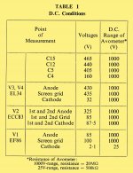
I spent some time going over the datasheet for GZ34/5AR4 and realised that there is a minimum resistance per plate that I'd not realised would need to be checked.
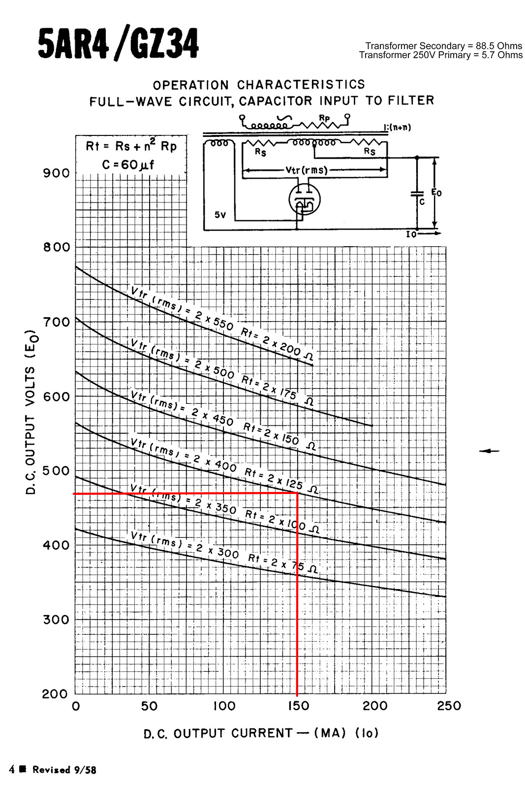
The valve wizard site also happened to have a handy formula for calculating it. (Rlim = Rsec + Rpri × (Vsec/Vpri)^2 + any extra resistance)
V Pri = 250
V Sec = 398
R Pri = 5.7
R Sec = 88.5
Result = 102.9464448
This put me a tad short of the 125 ohm minimum at 2x400V. (although they only list it for 60uF filter) I spent this morning having a good dig through my component stash and found a pair of 5W 60R vintage RS branded resistors which I've fitted in the 410-0-410 feeds from the HT fuses to the rectifier socket.

These are the measurements I got with these 60R limiting resistors in place. The numbers look significantly closer to the book figures now. I'm doing some testing this evening and will check with the camera to see if there is any sign of glow in the plates.
Mains voltage - 237.3Vac
HT voltage - 391Vac
C15 - 458Vdc
C12 - 441Vdc
C5 - 410Vdc
C4 - 165.5Vdc
V4 Anode - 431Vdc
V4 G1 - 0.7Vdc
V4 G2 - 433Vdc
V4 G3/Cathode - 30.9Vdc
Heater - 6.0Vac
V3 Anode - 431Vdc
V3 G1 - 0.6Vdc
V3 G2 - 432.5Vdc
V3 G3/Cathode - 30.4Vdc
Heater - 6.0Vac
V2 Anode 1 - 303.6Vdc
V2 Anode 2 - 303.7Vdc
V2 G1 - 88.4Vdc
V2 G2 - 80.4Vdc
V2 Cathode 1&2 - 92.8Vdc
V1 Anode - 88.8Vdc
V1 G1 - 0 (no signal)
V1 G2 - 110Vdc
V1 G3/Cathode - 2.1Vdc
Heater - 6.2Vac
Hello it is me again. So far every solution I came up with you refused. How am I supposed to help you?
To me you look like you have taken a lot of pride in assmebling that amplifier. Beautyful is simply a word not fitting enough to describe your work. Looks like after all you know what youre doing and youre doing it great! I wish I could that great of a job turret boards.
Most of the modifications I suggeseted were done 100% in practice. Some people tried connecting G3 to the GND (making it negative for the tubes). And some of those mods were done even here in this forum (just needs real digging in the posts).
Some of the things I am uncertain because I have not tried them myself or I have seen them in forums but I dont remember the certain results. I have built these amplifiers myself but I cant test everything for you. After all youre the deciding factor here to say wheter or not you like it. You have to try you have to experiment. Otherwise you wont gain any experience. Besides I would test this for you but once again my amps are PCB based and cant be easy modded like yours!
I hope you will consider my suggestions and try them. Deviating from the original schematic is not a big deal. You need to try, experience, decide. Dont fear change. You cannot do any damage if you follow my suggestions.
You are just on the edge of the 25 watts total EL34 dissipation there now at 26.4 watts.
Current is 30.9 volts over 470 ohms = 0.066A
Volts are Anode volts 431 minus cathode volts 30.9 = 400.1 x 66mA
So 400v x 0.066mA = 26.4W.
Personally I would still try to get south of the 25 watts.
Current is 30.9 volts over 470 ohms = 0.066A
Volts are Anode volts 431 minus cathode volts 30.9 = 400.1 x 66mA
So 400v x 0.066mA = 26.4W.
Personally I would still try to get south of the 25 watts.
That should read
Volts are Anode volts 431 minus cathode volts 30.9 = 400.1
So 400v x 66mA = 26.4W.
Volts are Anode volts 431 minus cathode volts 30.9 = 400.1
So 400v x 66mA = 26.4W.
Firstly, your have made a neat job, but personally I would use metal rather than wood. Both fire risk and also shielding from main hum and other external interference.
Secondly you should look at the following site "30W Push Pull amplifier designed by Claus Byrith". It can be accessed from the Lundhal transformer site.
Claus uses the Mullard 5-20 as the base of his design but makes some nice changes including reducing feedback, operating the EF86 as a triode and reducing the standing current in the EL34's.
I like to run output valves, in my designs, at 80% of their power rating. Your current operating point is above valve spec
- Home
- Amplifiers
- Tubes / Valves
- Testing newly built mullard 5-20