That's a very decent loopback test.
Are you aware going through the interface (SC in, SC out) you get a gain of 2? That might explain why you would be clipping the input of the SC.
Are you aware going through the interface (SC in, SC out) you get a gain of 2? That might explain why you would be clipping the input of the SC.
@ SY and ZigZagFlux: Thanks, I will experiment some more tomorrow. It may be that I am unfamiliar with the software, sound card, and my new interface.
@Pmillett: Nice project. Every single component from your list was available at either Mouser or Digikey. The PCB was perfect. Every component installed was precision matched to the PCB drilled holes. The silk screening made it easy. Well, I did put one OpAmp in backwards. That was completely on me.
@Pmillett: Nice project. Every single component from your list was available at either Mouser or Digikey. The PCB was perfect. Every component installed was precision matched to the PCB drilled holes. The silk screening made it easy. Well, I did put one OpAmp in backwards. That was completely on me.
Pete does a great job. My homebrew interface worked very well but was a mess compared to his.
Once you have it working, I can suggest a minor change that will increase its versatility.
Once you have it working, I can suggest a minor change that will increase its versatility.
Yeah, I was cleaning a drawer out last week, and stumbled upon mine. I remember thinking, Wow that's a dam good looking Board!
I'm think I better get to mine. It has been 3 years after all!!
I'm think I better get to mine. It has been 3 years after all!!
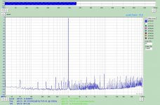
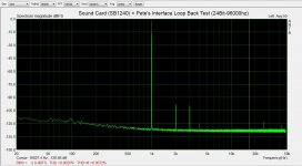
I recently did some mods on Pete's interface that have improved the performance, the first was replacing R2 and R16 with a two back-to-back MOSFETS with a resistor across the gates. The aim was to lower the Johnson noise caused by the two big overload protection resistors (without loss of protection). This reduced the noise floor to -130db-ish.
Great! However, this revealed that the SC Output was now the more noisy of the two halves of the box and any benefit of the reduced floor on the input was being swamped by the noise from the SC Output side of the box.
I also noted that the meter was reading quite a bit of AC noise, about 43mV, when the sound was switched off, but not when the 1/4" jack to the souncd card was unplugged (1/4" inputs ground with no plug) nor at first switch on when no signal had been though the SC Output, in either case it read 0.3mV.
With a bit of help from a friend who suggested I look for an oscillating driver op amp on the SC Output I eventually discovered that it was actually the receiver that was oscillating, but at quite a low level; this wasn't being shown up before but was made visible with the improvements to the input side.
I use the THAT Corp parts, but they do have a wider bandwidth than the BB parts which may account for the oscillation. I haven't tried the BB parts as I don't have any. I'm certainly not pointing any disparaging fingers at THAT Corp as I don't know the root cause; it could be a number of things.
To cure the problem, I added a small zobel across the op amp's inputs and achieved a consistent -100db THD and -86db THD+Noise 20Hz to 100kHz which I am very pleased with!
Its amazing there's all sorts of gremlins this low down! Anyway, the noise floor is almost 10db better than my previous posts and almost as good as a loopback test. (Please don't compare the previous post's THD measure as that was 20Hz to 20kHz so is an apples to oranges comparison).
Previous results with a PCI ESI Juli@ this is using an EMU 1212 PCIe http://www.diyaudio.com/forums/tubes-valves/155405-test-measurement-interface-soundcard-41.html
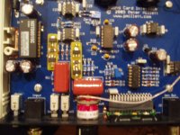
You can see the MOSFET input mod on two small daughter PCBs where the larger R2 and R16 resistors used to be.
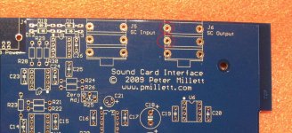
The zobel is 91R + 100nF in series across the pins marked in red on the blank PCB image.
Great! However, this revealed that the SC Output was now the more noisy of the two halves of the box and any benefit of the reduced floor on the input was being swamped by the noise from the SC Output side of the box.
I also noted that the meter was reading quite a bit of AC noise, about 43mV, when the sound was switched off, but not when the 1/4" jack to the souncd card was unplugged (1/4" inputs ground with no plug) nor at first switch on when no signal had been though the SC Output, in either case it read 0.3mV.
With a bit of help from a friend who suggested I look for an oscillating driver op amp on the SC Output I eventually discovered that it was actually the receiver that was oscillating, but at quite a low level; this wasn't being shown up before but was made visible with the improvements to the input side.
I use the THAT Corp parts, but they do have a wider bandwidth than the BB parts which may account for the oscillation. I haven't tried the BB parts as I don't have any. I'm certainly not pointing any disparaging fingers at THAT Corp as I don't know the root cause; it could be a number of things.
To cure the problem, I added a small zobel across the op amp's inputs and achieved a consistent -100db THD and -86db THD+Noise 20Hz to 100kHz which I am very pleased with!
Its amazing there's all sorts of gremlins this low down! Anyway, the noise floor is almost 10db better than my previous posts and almost as good as a loopback test. (Please don't compare the previous post's THD measure as that was 20Hz to 20kHz so is an apples to oranges comparison).
Previous results with a PCI ESI Juli@ this is using an EMU 1212 PCIe http://www.diyaudio.com/forums/tubes-valves/155405-test-measurement-interface-soundcard-41.html
You can see the MOSFET input mod on two small daughter PCBs where the larger R2 and R16 resistors used to be.
The zobel is 91R + 100nF in series across the pins marked in red on the blank PCB image.
Attachments
Great! However, this revealed that the SC Output was now the more noisy of the two halves of the box and any benefit of the reduced floor on the input was being swamped by the noise from the SC Output side of the box.
I also noted that the meter was reading quite a bit of AC noise, about 43mV, when the sound was switched off, but not when the 1/4" jack to the souncd card was unplugged (1/4" inputs ground with no plug) nor at first switch on when no signal had been though the SC Output, in either case it read 0.3mV.
With a bit of help from a friend who suggested I look for an oscillating driver op amp on the SC Output I eventually discovered that it was actually the receiver that was oscillating, but at quite a low level; this wasn't being shown up before but was made visible with the improvements to the input side.
I use the THAT Corp parts, but they do have a wider bandwidth than the BB parts which may account for the oscillation. I haven't tried the BB parts as I don't have any. I'm certainly not pointing any disparaging fingers at THAT Corp as I don't know the root cause; it could be a number of things.
To cure the problem, I added a small zobel across the op amp's inputs and achieved a consistent -100db THD and -86db THD+Noise 20Hz to 100kHz which I am very pleased with!
You can see the MOSFET input mod on two small daughter PCBs where the larger R2 and R16 resistors used to be.
The zobel is 91R + 100nF in series across the pins marked in red on the blank PCB image.
Hi, Andrew !
Thanks for so great post! This is what I have been looking for. I have noise/oscillation problem with Sound card interface, albeit at much higher level. I left home for vacation and didn't had much time to investigate it, and looks you already found both cause and a solution.
May I ask you to share few more details of your mode?
1) Zobel 91R + 100nF across SC output - may it cause HF roll-off if input resistance of DUT (device under test) will be several hundreds K (typical for tube amplifiers)?
2) When you referring to THAT corp - did you mean their transistor arrays or pre-amplifiers? Which exactly THAT Corp parts you have used in your mods?
3) Dauther PCBs - are they cut from standard prototyping PCB boards? What is schematic of MOSFET connection?
Thanks in advance !
1) Zobel 91R + 100nF across SC output - may it cause HF roll-off if input resistance of DUT (device under test) will be several hundreds K (typical for tube amplifiers)?
The zobel is across the input to U6, the diagram I posted is slightly wrong, it should be the two lower pins, when you turn over the board you'll see the tracks running to pin 2 and 3 on U6. You won't get it wrong! The zobel doesn't impact the output to the DUT as there is U6 the balanced receiver opamp and U1 the driver opamp before the signal reaches the DUT. I believe the idea behind U1 and U6 is to buffer the sound card's signal and amplify it by 2x so that the generator section can be certain to drive a difficult load at 2v RMS.
2) When you referring to THAT corp - did you mean their transistor arrays or pre-amplifiers? Which exactly THAT Corp parts you have used in your mods?
My opamp at U6 is a THAT Corp device not a BB device, Pete lists both opamps as compatible on the ATEST Bill of Materials; the THAT Corp part is higher bandwidth and slightly lower noise, that's all.
3) Dauther PCBs - are they cut from standard prototyping PCB boards? What is schematic of MOSFET connection?
Yes, exactly, old fashioned light box and ferric chloride etched PCB. I'll see what I can dig out for the schematic for the MOSFET, assuming there's interest?
We installed one set of the daughter boards on a friend's unit, both units show improved noise floors after the change.
Before going ahead and adding a zobel you might be best waiting for me to check I haven't reduced the freq response of the generator, I don't think I have but I haven't get checked; it was certainly all OK at 1kHz.
Andrew
Last edited:
Yes, I have changed the frequency response, I thought I may have used too bigger values but it was what I had to hand. I'll post up the better values as soon as I get chance.
Andrew
Andrew
I have completed my Sound Card Interface. I installed shielding as discussed in various post.
The first time I powered it up I new something was wrong. Took me a long time but I discovered that I installed U1 Op Amp backwards. With U1 installed correctly, I was able to calibrate the meter section.
Then I ran back to back loop test first on the usb sound card, and then with the interface and sound card.
I have never used any of the FFT spectrum analyzer software programs talked about here. So this is new to me. After player around with serveral FFT software programs, I settled on ARTA for the test.
I am going to buy a better sound card but for the time being I am using what I have. A Creative Labs X-Fi External USB Card.
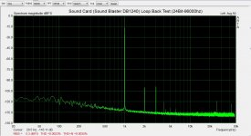
The first picture is: Loop back test of just the sound card.
The second picture is: Loop back test of both the sound card and the interface.
I thought the THD on just the sound card was not bad. But the THD of both is horrible.
Do you suppose I damaged U1 or some other component?
Ok I did a little trouble shooting. I did damage U1 when I inserted it backwards. Looking a the Sound Card Interface Generator Output on a scope (1khz applied to input) showed severe clipping.
I ordered a replacement op-amps (U1 - DRV134pa).
Now things are look much better.
I am still learning how to use the FFT software but here are a couple of screen shots of just the "sound card in loopback" and then "sound card and interface in loop back".
The noise floor does look a little higher through the interface. But it looks minimal and one would expect a some noise.
How does this look? Any concerns here?
.
Attachments
With a bit of help from a friend who suggested I look for an oscillating driver op amp on the SC Output I eventually discovered that it was actually the receiver that was oscillating, but at quite a low level; this wasn't being shown up before but was made visible with the improvements to the input side.
This doesn't sound like an oscillation to me... it sounds more like noise / RFI pickup at the input...
Could you see this signal with a scope? I'm curious what frequency it was...
Pete
This doesn't sound like an oscillation to me... it sounds more like noise / RFI pickup at the input...
Could you see this signal with a scope? I'm curious what frequency it was...
Pete
Perhaps you are right Pete, I did some more experimentation last night, the zobel idea cures the problem but causes a frequency roll off, if I reduce the values of the zobel to the point where I don't get roll off then I see noise again, so I'm pretty much back where I started.
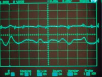
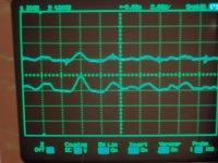
I have three screen shots I took of my scope,
On both "before receiver" and "after receiver" the lower trace is the BNC output, the upper trace is me looking for the first place that signal appears. The signal isn't there on the input to the receiver opamp U6 but it is there on the output of it.
Third image "bnc into scope", shows that lower trace in more detail, I used the cursor measures across one peak to trough, you can see that on the the left hand side the waveform; it has a freq of 240kHz. But the waveform is quite complex, at one point I wondered if it was related to the switcher.
On the other ATEST unit I got to play with the problem wasn't present, this used BB op amps (its your full kit) rather than THAT Corp and did not have had the switcher in a socket, this one does. The only other difference was it had copper tape on the sides of the box as well as the top and bottom of the case. I did the input MOSFET mod on both boxes.
The other box was tested with the same sound card, so I'm pretty certain its something related to the ATEST itself.
Andrew
Attachments

I have the same issue with ATEST sound card interface as AndrewL. Tested ESI Juli alone (with both balanced and unbalanced) and sure it is OK for 100%. With ATEST Juli connected in balanced mode.
Changed 3 USB power supplies to be sure this is not noise from USB - no result.
I think this could be caused
1) by Murata DC-DC converter used by ATEST
2) RF noise pick up (not sure because level is too high)
3) Oscillation
Andrew, what did you mean - "switcher in a socket" ?
Changed 3 USB power supplies to be sure this is not noise from USB - no result.
I think this could be caused
1) by Murata DC-DC converter used by ATEST
2) RF noise pick up (not sure because level is too high)
3) Oscillation
Andrew, what did you mean - "switcher in a socket" ?
I put the switcher chip in a socket like the op amp, rather than solder it direct to the board.
Andrew
Andrew
Is there a better USB DAC/ADC available than the Behringer UCA202? The noise floor seems to be around -105dB or so using a USB 3.0 Express card in my laptop. I'm using TrueRTA by TrueAudio. It's a 1/24th octave real time spectrum analyzer. I ordered the interface kit and was wondering if I should upgrade my DAC/ADC audio device.
Last edited:
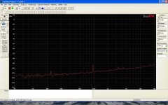
Here's a screen shot of the setup I put together. Generator was off. There's a strange artifact at about 1kHz. Is this considered good? I think it's just ok.
I would say OK but not sparkling, the 1k artefact, could it be a function of the way the maths works?
I would say OK but not sparkling, the 1k artefact, could it be a function of the way the maths works?
I don't really know. I'll check to see if it's there with the built in Realtek HD audio system. As I recall, the noise floor with that is worse by about 10dB.
So, still wondering about a USB ADC/DAC for use with this excellent interface.
I don't really know. I'll check to see if it's there with the built in Realtek HD audio system. As I recall, the noise floor with that is worse by about 10dB.
So, still wondering about a USB ADC/DAC for use with this excellent interface.
I think it may be a function of the maths, unless there's crosstalk;lk from another channel?
I don't know of a USB card, sorry.
Here's a screen shot of the setup I put together. Generator was off. There's a strange artifact at about 1kHz. Is this considered good? I think it's just ok.
Can you try the same with another software, e.g. ARTA ?
Can you try the same with another software, e.g. ARTA ?
Sure, later when I have time.
- Home
- Design & Build
- Equipment & Tools
- Test & Measurement interface for Soundcard