Pardon my ignorance
Isn't this what Chad at Acoustic Sounds did several years ago? I know he talked we big name Mastering Engineers about which signals and proper levels they desired to have when setting-up Lathes and Turntables.
Also, HiFi News did another one with test signals and music.
Both these LPs where meant to replace the oldies that CBS did many decades ago. Or the set that Bruel & Kjaer made.
As a minimum, levels and test signals can be infered by what those oldies provided. Then go from there.
Finally, there is an article on an old AES journal that proposed to perform Azimuth/VTA setting. I need to dig in my library to find the Authors and Title of said paper.
Ernst
Pinch warps, affecting just the outer rim, lead in and early grooves? They tend to be short in physical length, and so have a sort of 3-7Hz based FM modulation to pitch, though not many cycles. It can also take a time for the arm to settle afterwards ............Yes some kind of depression or bubble that effects the first centimeter or so, the side starts with left, right, left+right sweeps (60sec each). By the third sweep the effect is very small. I just didn't consider the extent of warpage could be so limited.
LD
Isn't this what Chad at Acoustic Sounds did several years ago? I know he talked we big name Mastering Engineers about which signals and proper levels they desired to have when setting-up Lathes and Turntables.
Also, HiFi News did another one with test signals and music.
Both these LPs where meant to replace the oldies that CBS did many decades ago. Or the set that Bruel & Kjaer made.
A fair question. The problem is that the newer ones don't even get in the same ball park as the classic B&K or CBS test records (the latest ortofon might), but also, with the processing power available to us now we can test things that were not possible in the 70s. Thanks mainly to Luckythedog who has spend most of the last decade questioning perceived wisdom there are things that we would like to measure that no available disks manage.
Some of this is fairly hard core vinyl optimisation though 🙂
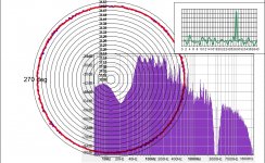
Here's a simulation by way of illustration of programme material with an embedded 3150Hz carrier, and an associated polar plot of pitch stability.
The test file was extracted from a 3rd party vinyl recording as to be reasonably dynamic and well recorded. A deep narrow notch-out centred at 3150Hz was made by using eq filters in Audacity, and a 3150Hz mono tone mixed in at a level consistent with the average spectrum.
Attached is a polar plot which shows, as expected, a perfect circle from the synth 3150Hz tone, and small errors associated with programme material effect on measurement. Inset is the spectrum of the test file, averaged over the two revolutions - one can see the notch, and the 3150Hz carrier tone is matched for level with programme material.
If a test file like this were used for real playback, one would be able to observe the effect of dynamic variation in programme material on pitch stability, either associated with variation in drag or associated with cart/arm instability.
Included is the test file used, for the python boys to confirm it also works in that method, which it should methinks.
This isn't a candidate for a test-record file, BTW, just an illustration and test that the method works.
Interesting?
PS: Haven't a clue what the ~28Hz residual ripple spectral peak is............. perhaps an artefact of the digital eq used to create the test file?
LD
Attachments
Last edited:
What I mean is the exact choice of programme material and level of carrier is an open question. It looks like it could work, that's all.This isn't a candidate for a test-record file, BTW, just an illustration and test that the method works.
LD
Who makes new cutting lathes nowadays ? I am sure new ones will be more advanced and improved.
I am saying this without taking anything away from high quality vintage lathes.
Regards.
I am saying this without taking anything away from high quality vintage lathes.
Regards.
Interesting?
PS: Haven't a clue what the ~28Hz residual ripple spectral peak is............. perhaps an artefact of the digital eq used to create the test file?
LD
One thing, IME that notch is going to fill up big time with real LP play.
ahh OK Bill.
A little curious (amusing) thought occurred to me. Instead of using linear cutter head why not use a pivoted cutter head to lower the cartridge alignment distortion/s. Will that help in test record having any advantage over generally available other test record.
Regards
A little curious (amusing) thought occurred to me. Instead of using linear cutter head why not use a pivoted cutter head to lower the cartridge alignment distortion/s. Will that help in test record having any advantage over generally available other test record.
Regards
Whilst that is mechanically possible, you would have to optimise for one particular arm length and alignment, so would be a heroic bit of engineering for a reduced market share. It would be easier to rotate the cutting head to get the same effect.
Better would be to persuade people to use linear tracking arms!
Better would be to persuade people to use linear tracking arms!
Re Post #261: Here are two.
J.AES 1965 13, 3 pp. 241-247. J. G. Woodward, “Techniques for Measuring the Vertical Tracking Angle of Stereophonic Phonograph Pickups”
J.AES 1979 27, 4 pp. 242-249. James V. White; Arthur J. Gust, “Three FM Methods for Measuring Tracking Angles of Phono Pickups”
J.AES 1965 13, 3 pp. 241-247. J. G. Woodward, “Techniques for Measuring the Vertical Tracking Angle of Stereophonic Phonograph Pickups”
J.AES 1979 27, 4 pp. 242-249. James V. White; Arthur J. Gust, “Three FM Methods for Measuring Tracking Angles of Phono Pickups”
Ah, the deep eq notch is made into programme material before the carrier is mixed with it. Thus the master track has the notch (and the carrier) throughout the test track.One thing, IME that notch is going to fill up big time with real LP play.
However, harmonic distortion from programme material can't be kept out of the notch during playback. This is why it's necessary to think through what amplitude the carrier should be, to ensure an adequately clear carrier no matter what programme material is.
One could simply opt for large carrier amplitude, but the aim is not to interfere with the effect of dynamic variation in programme material level on stylus drag, so keeping the carrier amplitude small as possible helps this.
Harmonic distortion can be simulated in the time domain as a separate track and mixed in, at least for the first couple of orders........I'll give it a go..............
LD
The first one is very promising, the abstract describes a new test LP track.
On the first page of this thread there is a large bibliography, Compliantie/massa- database: intro- txt Woodward published in the IEEE journal also which I could get if need be.
Lots of info here, patents etc. - VTA
CBS patent on VTA/tracing distortion meter here - US4359768A - Vertical tracking angle meter
- Google Patents
Patent says CBS STR112 already has this track, I guess this means I have to get on it.
Last edited:

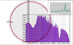
OK, here's that simulation, same levels and this time including simulated effects of harmonic distortion.One thing, IME that notch is going to fill up big time with real LP play.
2nd harmonic added at -20dB, 3rd harmonic at -30dB. Based on time domain generation of harmonics generated from programme material and mixed into the original track. One can see the notch filling up, as you say.
However, from the attached polar plot, one can see the resulting error is barely affected, and still looks fine, which is good news.
Also attached is the audio file - would be interesting to confirm that the python SW also works at this S/N? I think the simulation's more realistic now, and bodes well for a workable test at quite modest carrier level.
LD
Attachments
I think the simulation's more realistic now, and bodes well for a workable test at quite modest carrier level.
LD
By eye that looks OK, but I'll need to check it in Python. BTW I would really appreciate your read on that CBS Labs patent. From a quick look the post processing is trivial in software and having correct VTA as a simple computation from a test track would be nice. The patent has expired so we can do whatever works.
That 28Hz is bothersome, maybe I can find the source from your files.
Hi everyone
Great idea and count me in. I read most of the post some are a little hard for me too follow but i dont recall seeing the objectives set out. Is this a record to setup the cart/ arm / table optimally or is a record to measure the performance of reproduction chain including the preamp? It would be good to agree on what type of instruments will most folks use .... 2ch oscilloscope is probably the minimum, some might have distortion meter, some might have spectrum analyser or FfT, some might digitize and apply the above in software.
I own two vintage test disks (stero review SRT 14A & CBS STR130) and something neither contains is a two tone test like used for IM tests.
Finally when choosing the mastering/pressing it would be good to ask those places to confirm what specs they are willing to guarantee and with what margin of error to make decision.
Instructions on how to use each track and to wire the setup is what most test discs lack. There are many tricks possible with X-Y mode on a scope and how one uses left and right channels. See shure c/pek-2 & c/pek-3 for ideas.
Once again good idea seems like a bunch of very smart folks here to make it happen with the attention to details this requires.
Look forward to it.
Paba
Re: AES papers
The second paper is the one that I was quoting. Also one of the tests was on CBS STR-112. The authors also have another paper "Measurement of FM distortion in phonographs" JAES 27(1979)121-143. The paper is full of equations, but the gist of all, is that with two test tones 400Hz/4kHz (also, in STR-112) tracking distortions can be measured easily!😕
It is similar to what Dale Manquen proposed to apply for wow/flutter measurements on Reel-Reel Recorders to pinpoint mechanical errors on the whole tape transport: idler, capstan, rollers, etc.
Ernst
PS, I have access to the AES library if it is as pdf, I should be able to get it. Pm me.
Re Post #261: Here are two.
J.AES 1965 13, 3 pp. 241-247. J. G. Woodward, “Techniques for Measuring the Vertical Tracking Angle of Stereophonic Phonograph Pickups”
J.AES 1979 27, 4 pp. 242-249. James V. White; Arthur J. Gust, “Three FM Methods for Measuring Tracking Angles of Phono Pickups”
Yes - the fundamental principle that magnitude of 400Hz FM correlates with tracking angle error, be it vertical or lateral error, is sound. It should suit a modern SW approach wellBTW I would really appreciate your read on that CBS Labs patent. From a quick look the post processing is trivial in software and having correct VTA as a simple computation from a test track would be nice. The patent has expired so we can do whatever works.
Consider a vertically modulated groove at 400Hz sine tone at reasonably high modulation level. A straight groove with sine shape hills and dales.
The effect of cutter head VTA is to make the shape of the down-slopes steeper and up-slopes more gentle. This effect is, in principle, exactly cancelled by cartridge VTA during playback. However, whenever there is a mismatch (as generally there is in real playback, significantly) effectively the stylus traverses the groove faster on one slope than the other.
If a relatively small 4kHz carrier tone is mixed with the 400Hz tone, that carrier will increase and decrease in frequency as the stylus traverses the 400Hz grooveshape, by an amount depending on any mismatch in VTA between cutting and playback.
Then demodulating the 4kHz carrier and looking at magnitude of 400Hz component is a measure of VTA error. Essentially, it's like looking at the inset graph on my polar plots, except extended to include 400Hz bandwidth.
Same works for lateral modulation, as a measure of tracking angle error.
So we already have the hard part of the SW, just need to think through calibration and whether 400/4kHz is optimal - it probably is. Has to be ~400Hz to avoid platter/cart/arm FM, carrier has to be slow enough to avoid drop-out or mistracking, but a push up to about 8kHz or 10kHz could be fine these days perhaps.
One wrinkle mentioned in the patent is that mistracking also induces 400Hz FM, when one thinks about it the stylus is taking a different path and so must change relative speed. So need to avoid mistracking, unless that is considered a feature........or reject it...... .......the phase of FM modulation is different between mistracking and tracking angle error conditions - it happens at a different time in the 400Hz cycle. So it could also be a very fine test of the onset of mistracking, when the stylus rides up one groove wall only..........or ignored if one can guarantee no mistracking.
LD
- Home
- Source & Line
- Analogue Source
- Test LP group buy